Search
Star
Feedback
Setup for Free
© 2026 Hedgehog Software, LLC
Twitter
GitHub
Discord
System
Light
Dark
More
Communities
Docs
About
Terms
Privacy
@shibo can you review this schematic if - tscircuit
t
tscircuit
•
8mo ago
•
41 replies
Mustafa7
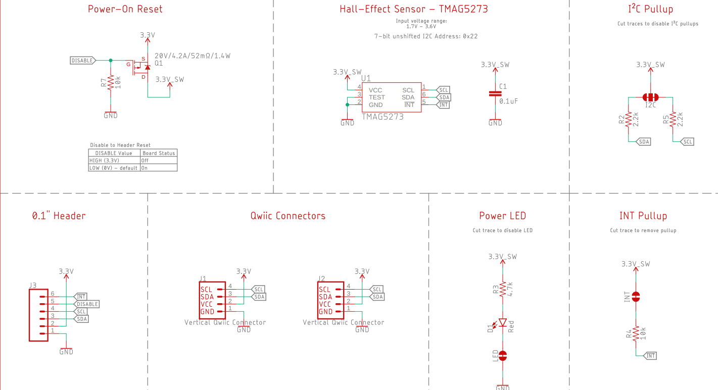
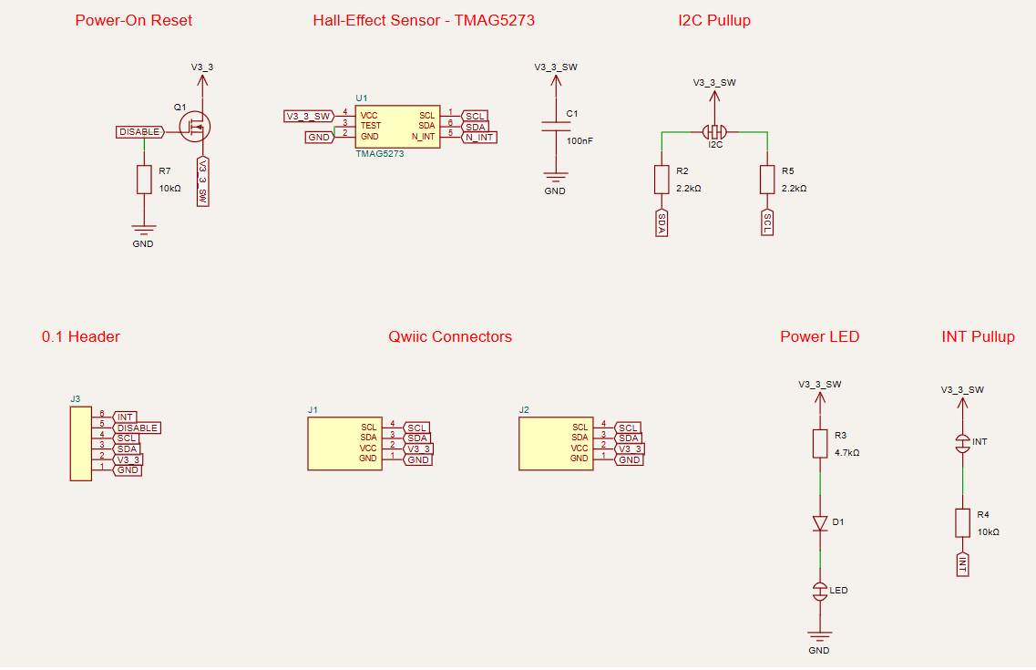
@shibo can you review this schematic if
@shibo can you review this schematic if its correct
tscircuit
Join
The community & user server for tscircuit. Build electronics with React & AI. Render code into schematics, PCBs, 3D, fabrication files, and more.
487
Members
View on Discord
Resources
ModelContextProtocol
ModelContextProtocol
MCP Server
Similar Threads
Was this page helpful?
Yes
No
Similar Threads
@shibo look at this schematic image, see
t
tscircuit / contributor
6mo ago
@shibo newer versions of schematic-
t
tscircuit / contributor
6mo ago
Sofiane - @Seve can you review this: https://gi...
t
tscircuit / contributor
4mo ago
@shibo if you injected a script tag with
t
tscircuit / contributor
6mo ago