Seve - @shibo @Anas this is the technique we're...
@shibo @Anas this is the technique we're going to be using for making "Kapton Tape Solder Masks", https://hackaday.io/project/1554-making-a-solder-mask-using-kapton-tape/details
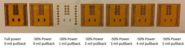
Note that they mention a "pullback" for the solder mask- this is similar to solder mask margin and yea we might want to have it be configurable at the time of LBRN generation- it basically lets me cover more or less of the pads
| Details | Hackaday.io
<p><strong>One-Off Solder
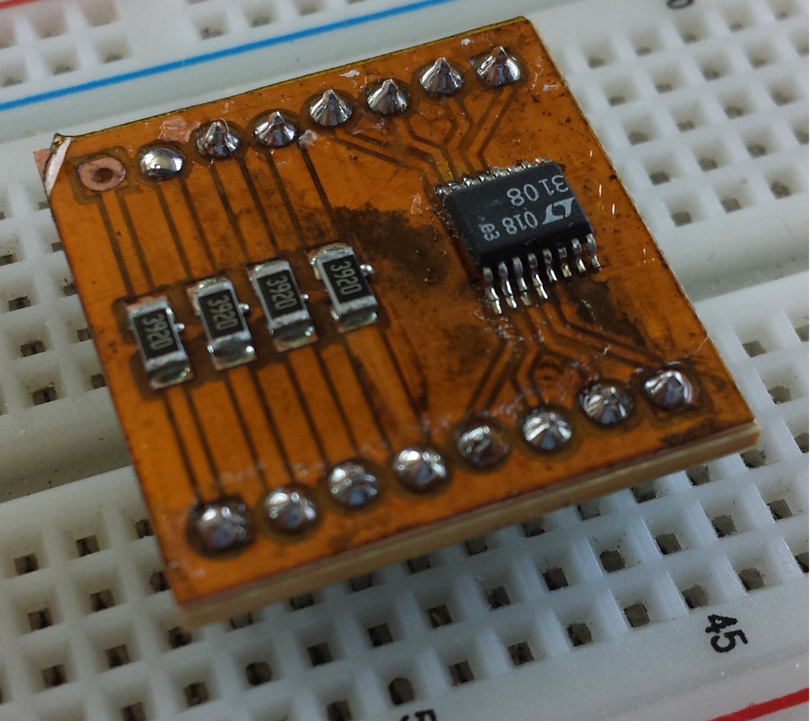
Mask </strong></p><p>This document outlines how to take an EAGLE layout, a printed circuit
board manufactured using the Protomat C60 circuit board cutter, Kapton tape (1
mil thick), and a Universal Laser VLS 3.50 to create a solder mask for your
circuit board. Figure 1 shows the finished
product; a cut circuit board co...

11 Replies
@Seve implemented new settings for soldermask
https://github.com/tscircuit/circuit-json-to-lbrn/pull/26
yes but just be aware that until we fill the soldermask i can't use the code
i don't know how to do fills, you will probably need to inspect a simple lbrn2 file with lightburn and make sure lbrnts does it correctly- this is the most important thing to do because it is the most work, and if i have to do it on monday it will set the project behind
@Seve
I’ve updated the soldermask layer generation so it should work better with our Kapton tape (polyimide sheet) laser-cutting workflow. The current output uses outline paths, which only trace the pad edges, but for Kapton tape we need the laser to clear the entire pad area rather than just outlining it.
Based on what I’ve found so far, and with some help from AI, switching the soldermask’s CutSetting from Cut mode to Scan mode seems like the right direction. Scan mode fills the shapes completely, similar to LightBurn’s raster/fill behavior. I also added scanOpt: "individual" so each pad is filled separately and doesn’t accidentally bridge to others.
and if I was right, I think we should need to update
generateLightBurnSvg fn to create filled svg shapesYes!
https://github.com/tscircuit/circuit-json-to-lbrn/pull/28
Can u review again. 😓
So i would avoid drawing the svgs as filled shapes
You should compute the scan path and show that

Scan path? I believe it's just a filled shape/outline
All shapes are “filled” with a special cut path, eg crosshatch, zfill etc
The laser always has to cut in a pattern because of the way ablation works- the “stroke width” is fixed (technically called focal point spot size)
now we just want to visualize that path correct?
yep!
i'll be using the laser tomorrow so we should make sure that we can correctly draw different fills so that i can preview then run it and test results