HVAC booster fan controlled by Arduino Nano.
Hello folks, happy NY to everybody.
There is one of my recent projects I ‘d like to share with you.
It is a booster fan for HVAC system in my house. We use a few of them to redistribute airflow around house and they do the job. The issue with them is they have to be readjusted \ reconfigured from time to time due to fact their threshold is being changed all the time and HVAC system switches from heating to cooling.
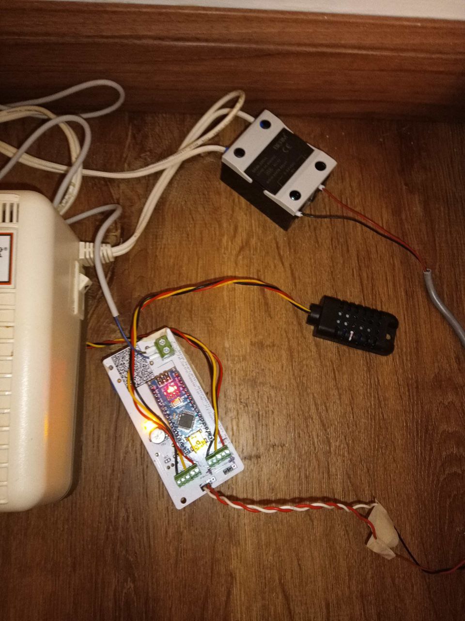
So I decided to do something about it and I have. What I have done is I designed and made a small control PCB with 2 temperature sensors (one measures an air flow in the duct and the second - a room temperature ) and Ard Nano to read these sensors and to control the fan.
The code works as following–
During boot time I initialize all peripherals (these 2 x AMD3201 \ DTH21 sensors) and turn Fan on for 2 sec for self-test.
Then I start looping and every 5 seconds I check these 2 sensors and calculate the abs value of difference between them. That it , using this approach makes it working for heat and for cold the same way .
If difference is above 18 C – I turn the fan on.
If difference is below 12 C - I turn the fan off.
All other cases - no changed in fan condition.
As for a fan I checked 2 options -
a. Using 24DC 150 mm fan.
b. Using 120VAC OEM fan controlled by SSR.
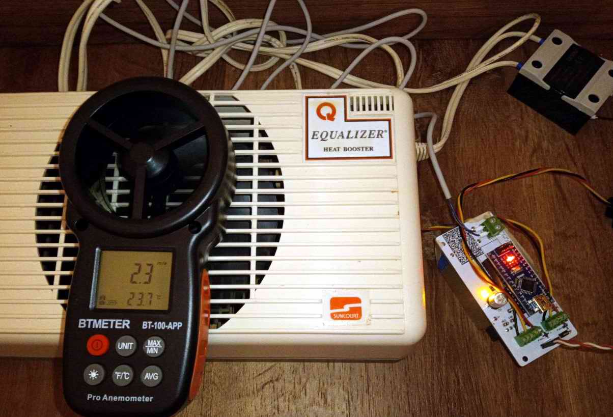
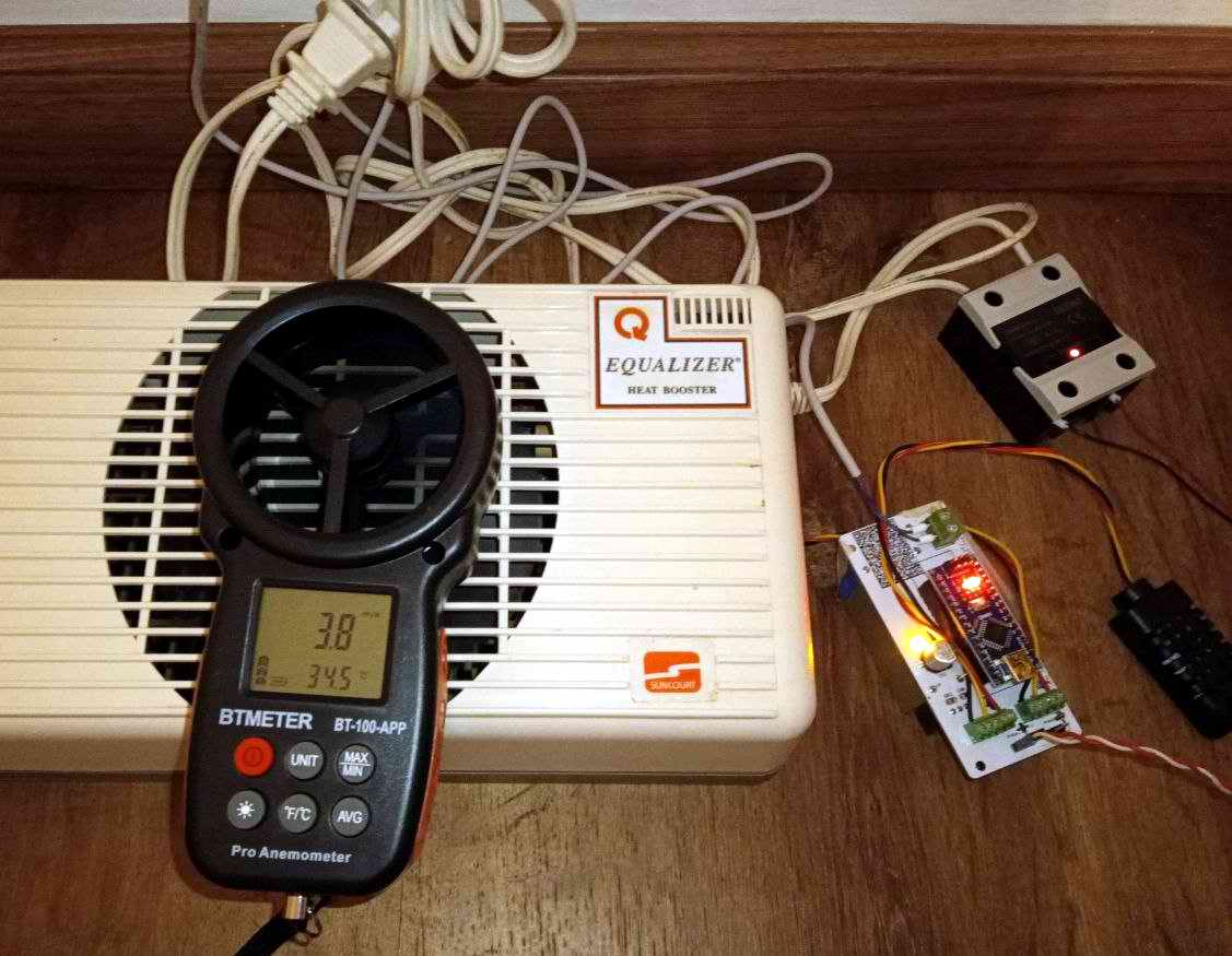
Option A was rejected by my wife due to high level of noise. So for now I am sticking to option B . The prototype is shown on these pictures. You can see how this fan boosts the air flow. When the fan is Off, the air flow is around 2.3 m\s, and when it is On - 3.7m\s.
My next step is (and I am on it) to design and 3D print a new enclose to enclose all these components.
Please let me know what you think. Thank you.
There is one of my recent projects I ‘d like to share with you.
It is a booster fan for HVAC system in my house. We use a few of them to redistribute airflow around house and they do the job. The issue with them is they have to be readjusted \ reconfigured from time to time due to fact their threshold is being changed all the time and HVAC system switches from heating to cooling.
So I decided to do something about it and I have. What I have done is I designed and made a small control PCB with 2 temperature sensors (one measures an air flow in the duct and the second - a room temperature ) and Ard Nano to read these sensors and to control the fan.
The code works as following–
During boot time I initialize all peripherals (these 2 x AMD3201 \ DTH21 sensors) and turn Fan on for 2 sec for self-test.
Then I start looping and every 5 seconds I check these 2 sensors and calculate the abs value of difference between them. That it , using this approach makes it working for heat and for cold the same way .
If difference is above 18 C – I turn the fan on.
If difference is below 12 C - I turn the fan off.
All other cases - no changed in fan condition.
As for a fan I checked 2 options -
a. Using 24DC 150 mm fan.
b. Using 120VAC OEM fan controlled by SSR.
Option A was rejected by my wife due to high level of noise. So for now I am sticking to option B . The prototype is shown on these pictures. You can see how this fan boosts the air flow. When the fan is Off, the air flow is around 2.3 m\s, and when it is On - 3.7m\s.
My next step is (and I am on it) to design and 3D print a new enclose to enclose all these components.
Please let me know what you think. Thank you.