Send a signal down a wire, detect wire is open/shorted, & transistor on or off, send analog back.
"Op wants to send a signal down a wire, detect if the wire is open or shorted, and if the transistor is on or off, sent back as a single analog voltage" -AnonEngineering
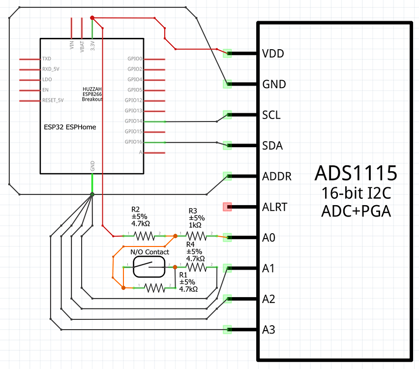
This is basically how it is working with a contact reed switch:
Falstad simulation:
https://tinyurl.com/2og439a8
You will see here when you open the Magnet reed switch the voltage on the analog input will alter between 1.1V (ON) & 1.65V (OFF). If you click the "Short Test" this is simulating someone connecting the 6 meter wires together some place between the contact and the input. Say they put a nail through the cable or something else the voltage would go to 0V on the Analog Input. If someone cut the wire the voltage would go up to 3.3V on the Analog Input.
I want to do the same but for a line going to an Output from the Arduino that will control a transistor to turn other things on and off like a Piezo Siren or Relay but sense if the wire has been cut/shorted/on/off with an analog input just like what was happening in the prior example with the magnetic contact.
I tried earlier in the live chat which AnonEngineer helped a lot then started to get browbeat by others when I wasn't understanding how to use the information they were relaying. Which is fine if it had some useful intention with forward progress.
We got the simulation to a point where it seems a little over the top which looks like this: https://tinyurl.com/2ha3hb88
I'm not sure what to do with the resistor network suggested by MaderDash which is where the forward progress died.
The relay voltage seems to be going haywire at the bottom left not sure if just a sim bug.
I understand basic concepts of resistor networks and voltage dividers but not how I should implement them to make this work or if I need them at all for a different way.
There is far too many wires involved now (6) going back to the Arduino to sense and control this one device in the simulation as the cables IRL have only 4 conductors that were used for connection.
30 Replies
It was suggested that I just read the cut/short state with the resistors on the Analog input and then just keep track of the on/off of the transistor on the processor. I would like all 4 states working just like the contacts by reading the one analog pin for redundancy sake of having endless analog inputs all functioning the same way.
I also can't wrap my head around how I would do the same thing for a Hall effect sensor instead of using a magnetic reed switch.
There are only 4 wires going to each sensor/device normally only 2 of the 4 used. Optimally I would only like to use 2 which may not be plausible as I would probably have to sense with the analog near the device so max 3 wires?
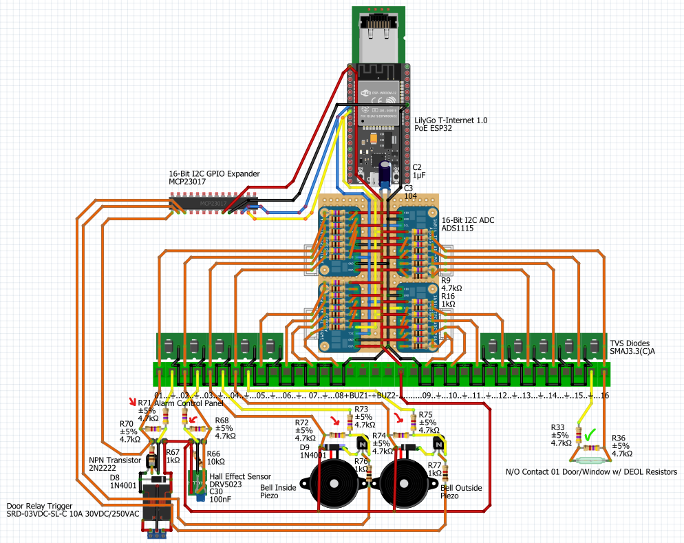
It's basically a mockup of a security/sensor system for my house and wanted to know if the wires were damaged in someway so I don't expect that the system is working when it is not.
It currently looks like this and it is just sensing if doors or windows are open to tell me to close them if it is raining etc. I would eventually like to add things like smoke sensors to it and other things that I would like to know the condition of their wires as well.
Ignore the components on the output devices of the picture as I was just guessing at what I would need to sense and control them.
The code to detect the 4 states basically looks like this for the contacts https://create.arduino.cc/editor/NonaSuomy/3e46c974-87aa-488f-9e6c-3902c291f3b1/preview
Arduino Cloud
The Arduino Web Editor allows you to write code and upload sketches to any official Arduino board from your web browser (Chrome, Firefox, Safari and Edge) after installing an agent.
The current sim falls apart where when you cut all/some of the lines or short them to all the other lines the voltage is not the same as the contact example. As there are now way too many wires to "monitor".
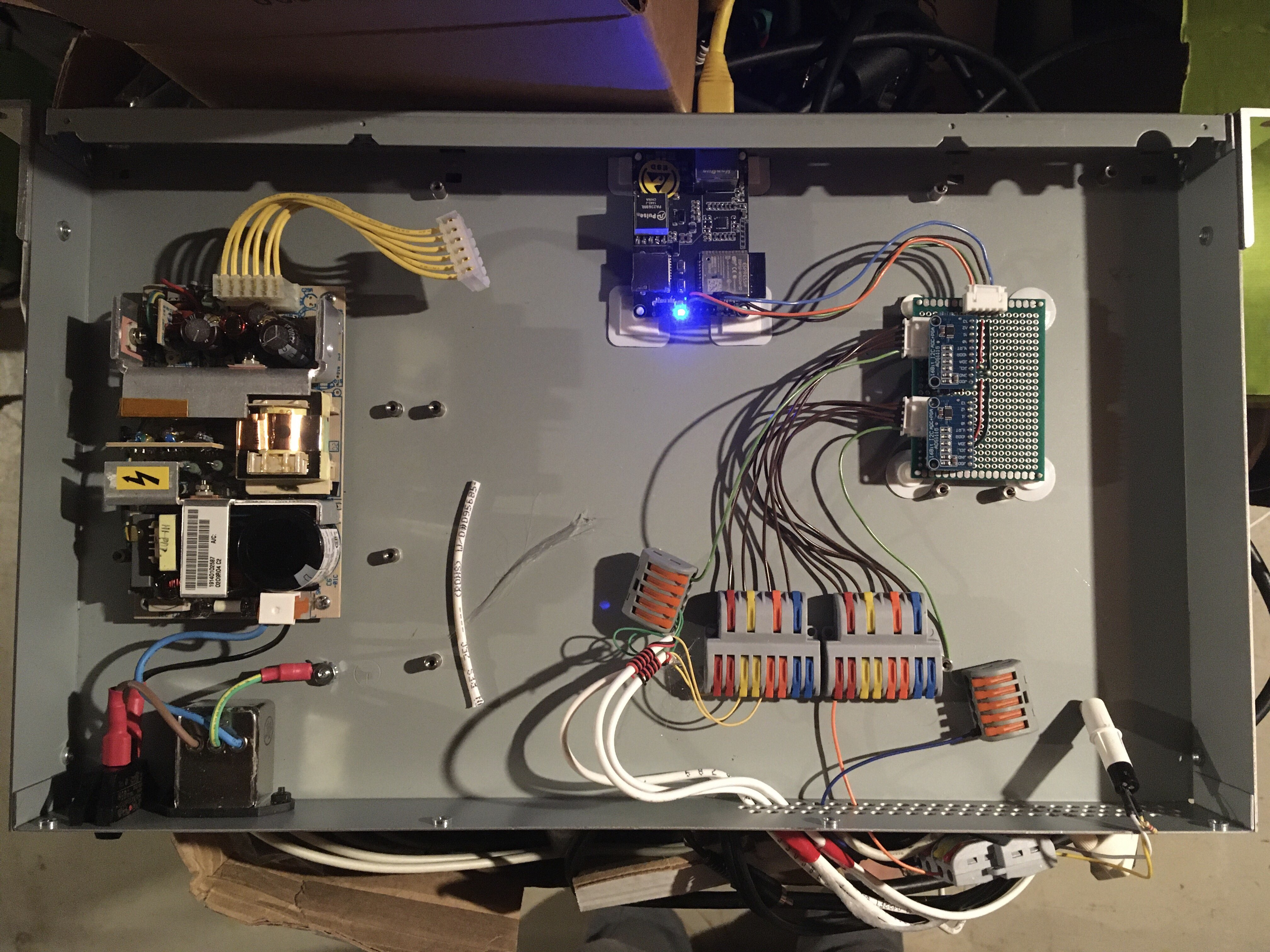
Currently 3 doors hooked up that play a sound when open.
Unknown User•3y ago
Message Not Public
Sign In & Join Server To View
This is basically just for fun not for profit, life and death are not going to be weighing on this system.
Extra stuff like smoke sensors will just be additional things to add to all ready working industry stuff to get notifications as well.
I would be publishing the end results on github which should be pretty straight forward.
This has nothing to do with industry standard professional stuff.
It currently works how I wanted it with detecting line states for contacts. I just couldn't wrap my mind around how to then do the same thing for an output line.
I've seen other people use a comparator on the line instead of an analog input but I like the idea of seeing multiple states with the different voltage values to determine that. Which worked how I set it up.
I just want to reuse all the old installed gear on the house to replace the mainboard that no longer functions. Mainly for my family to play with. Like right now the door sensors are being used to shout out cartoon lines when they open the door. Which brings a smile to their face. I thought it would be cool to take the window sensors and if the weather report says rain to tell the fam to close the windows.
The relay was to control a garage door opener. The hall effect sensor detects a magnet on the chain drive of it to tell if the door is open and closed.
I don't believe that home security boards are very advanced from what I have seen on them. Basically just doing what I'm doing except at higher voltages for longer runs to decrease noise. Nothing I'm doing is advanced.
The application of it really doesn't matter. It's basically just using an analog pin to detect voltage states and a digital pin that outputs to turn devices on/off.
Older units it was just a comparator, newer units it's just an analog pin. Each pin on a security system board they call Zones so one door contact can be one Zone. Then in the panel you can set your resistor value for the zone, then it detects that resistor value to tell you the line is not in a trouble state.
You can chain multiple contacts together for 1 zone as well. As you were saying, they put the End Of Line resistors at the end of that chain.
You can also on some systems put different resistors values on different contacts in that chain which is called zone doubling. It can then detect different devices per zone input by those different resistor values.
Right now I just have one contact or device on one pin (zone) none of them in serial to make it easy for me to understand.
basically looks like this which is shown in the first simulation:
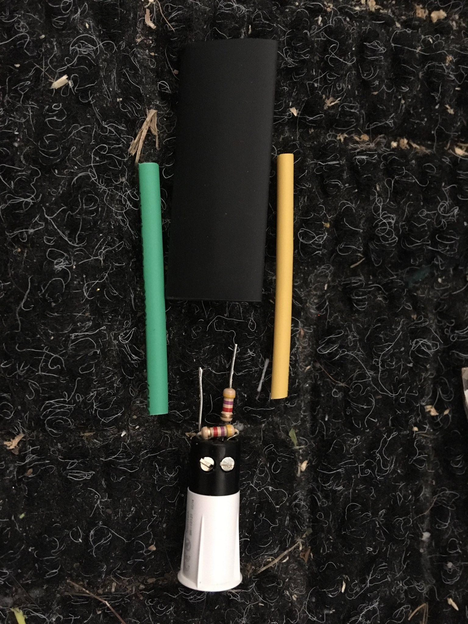
This is one of the many hardwired embedded door/window contacts you can see the double end of line resistors there.
Unknown User•3y ago
Message Not Public
Sign In & Join Server To View
That is not my question and technically if this was solved it would operate the same way except for the voltage level they normally use 12V.
Unknown User•3y ago
Message Not Public
Sign In & Join Server To View
I don't have really long runs so it's really not a concern.
What industry standards would you like me to adhere to?
Eventually it would feature creep this simple straight forward project into a non existent 20% completed bin project. Which I'm not a fan of.
Unknown User•3y ago
Message Not Public
Sign In & Join Server To View
Not going to UL certify this.
Unknown User•3y ago
Message Not Public
Sign In & Join Server To View
Then add end to end encryption etc.
Battery backup
Unknown User•3y ago
Message Not Public
Sign In & Join Server To View
battery charging
Unknown User•3y ago
Message Not Public
Sign In & Join Server To View
The wire in the wall is not twisted pair
My issue I was having is I’m not sure what the circuit should look like to sense these states on an output pin.
ie when you take the contact out of the layout above and then have the transistor there instead.
Do you have any information on what the circuit should look like to read a digital output going into a transistor with a single analog pin and have 4 states addressed?
The analog pin should see 1.1V (ON) & 1.65V (OFF) of the transistor state. 0V (Short) 3.3V (Cut) state of the cable from the single Analog Input attached to the digital pin some how.
Unknown User•3y ago
Message Not Public
Sign In & Join Server To View
At what part were you in? All you did was cause me to do some mental gymnastics and dance around the bush.
Unknown User•3y ago
Message Not Public
Sign In & Join Server To View
Thanks for the suggestion. Someone said something about how transmission lines work maybe that was along these lines. Does it matter how long the cable is?
Yes reject my reality and substitute your own. You detect shorts for if something is going on in your house. Renovations, hanging a picture frame, anything really that is a metal object that could go through your cable. Then the system says everything is fine because the circuit is completed by that foreign debris. Even corrosion or other elemental issues. I had my garage door sensors corrode with this exact issue.
I just didn’t get why he needed to say anything. Reminded me of someone yelling “I’m leaving now if anybody cares and you should all come with me and don’t help this person because they type a lot.” He barely said anything besides that he wasn’t willing to help twice. Ok… thank you?
I used to work with this 70yr old dude wish he was still around. I could go up to him and say this is what I’m inputting and this is what I want out. With in five mins he would dump a circuit onto a napkin and it would work flawless. No google or anything. Hopefully machine learning gets to this level someday. I popped this question in chatgpt and bard it basically is almost there just needs to work on its ascii art skills.
I think you can close this post at this point. As its clear nothing constructive is going to come from it. @NonaSuomy
Also my mobile device removes the enter key while typing in discord. Then I have to go to the computer to put stuff in paragraph format.
another reason not to message on mobil. 😄 have a great day.