Newbie question: Common Anode 4-digit 7-segment display circuit
Should I use resistors in my display circuit, or will it only dim the leds? So I found circuit examples online for both ways (with resistors on the digit pins and without), and I am not sure how to make the circuit. I have a SH5461AS display, which I found out was CA. I understood how the display works internally, but I'm not sure if I can skip using resistors in the circuit. Thanks for the help in advance!
27 Replies
Unknown User•2y ago
Message Not Public
Sign In & Join Server To View
Oh, right. So I just want to connect the display, that's on the breadboard, to my Arduino Uno digital inputs with jumper wires
I don't really know how to draw schematic yet
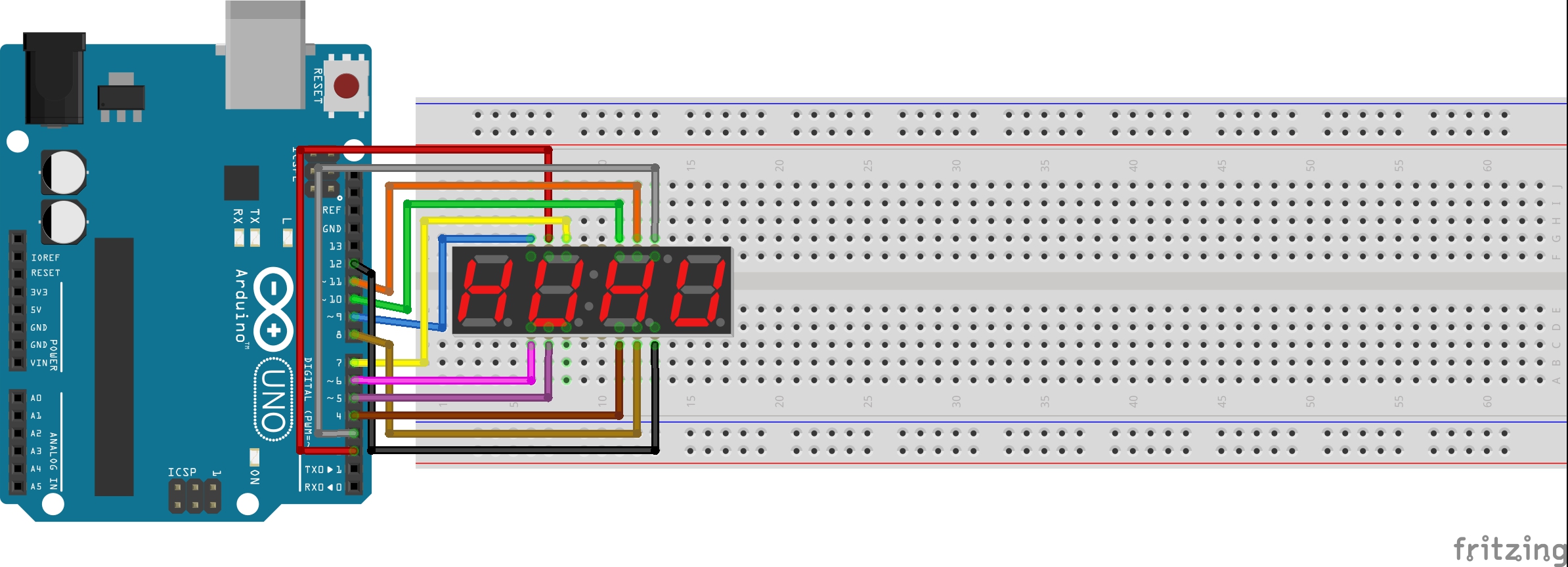
This is on Arduino Project Hub. I want to do something like this for now. But it is not specified what type of display was used in this project. So I wasn't sure if I should try or it would fry my display if resistors are needed
Unknown User•2y ago
Message Not Public
Sign In & Join Server To View
Alright. So I tested and I have more questions now. Thank you for your help in this problem 😄
So basically I need to set my segment pin to HIGH if I want a segment to turn on, but I have to set a digit pin to LOW if I want that specific digit to turn on. That means that I send the current from the outputs that are connected to the segment pins, then the digit pin if set to LOW lets that current through, hence turning the LEDs on, then the current leaves the display through that digit pin back to the digital output of the board. Or am I wrong with this?
If I'm right, and the LED segments receive the current from their output, and the current leaves through the digit pins, then wouldn't it be enough to place resistors on those pins, so the current gets lowered before entering back to the board
Unknown User•2y ago
Message Not Public
Sign In & Join Server To View
So based on my test run a bit earlier it seems it is common cathode (that's common ground, right?), because they lit up when set HIGH
Unknown User•2y ago
Message Not Public
Sign In & Join Server To View
So to be clear what I wanted to say: the first digit is turned on (showing the number 1)when A and B segments are HIGH, and D1 pin is LOW
Unknown User•2y ago
Message Not Public
Sign In & Join Server To View
Yes
Unknown User•2y ago
Message Not Public
Sign In & Join Server To View
Result:
Unknown User•2y ago
Message Not Public
Sign In & Join Server To View
I set it up like that, yes. Though only with 220Ohm resistors
Unknown User•2y ago
Message Not Public
Sign In & Join Server To View
Result:
Unknown User•2y ago
Message Not Public
Sign In & Join Server To View
Where can I draw schematic, so I can show you what I did?
Unknown User•2y ago
Message Not Public
Sign In & Join Server To View
Thank you!
Unknown User•2y ago
Message Not Public
Sign In & Join Server To View
Result:
Unknown User•2y ago
Message Not Public
Sign In & Join Server To View
Okay. So basically I need to use stronger resistors, and I need to use them on the segment pins as well, right?
Unknown User•2y ago
Message Not Public
Sign In & Join Server To View
Thank you!