Search
Star
1.4k
Feedback
Setup for Free
A
Arduino
•
13mo ago
•
29 replies
haydena_59
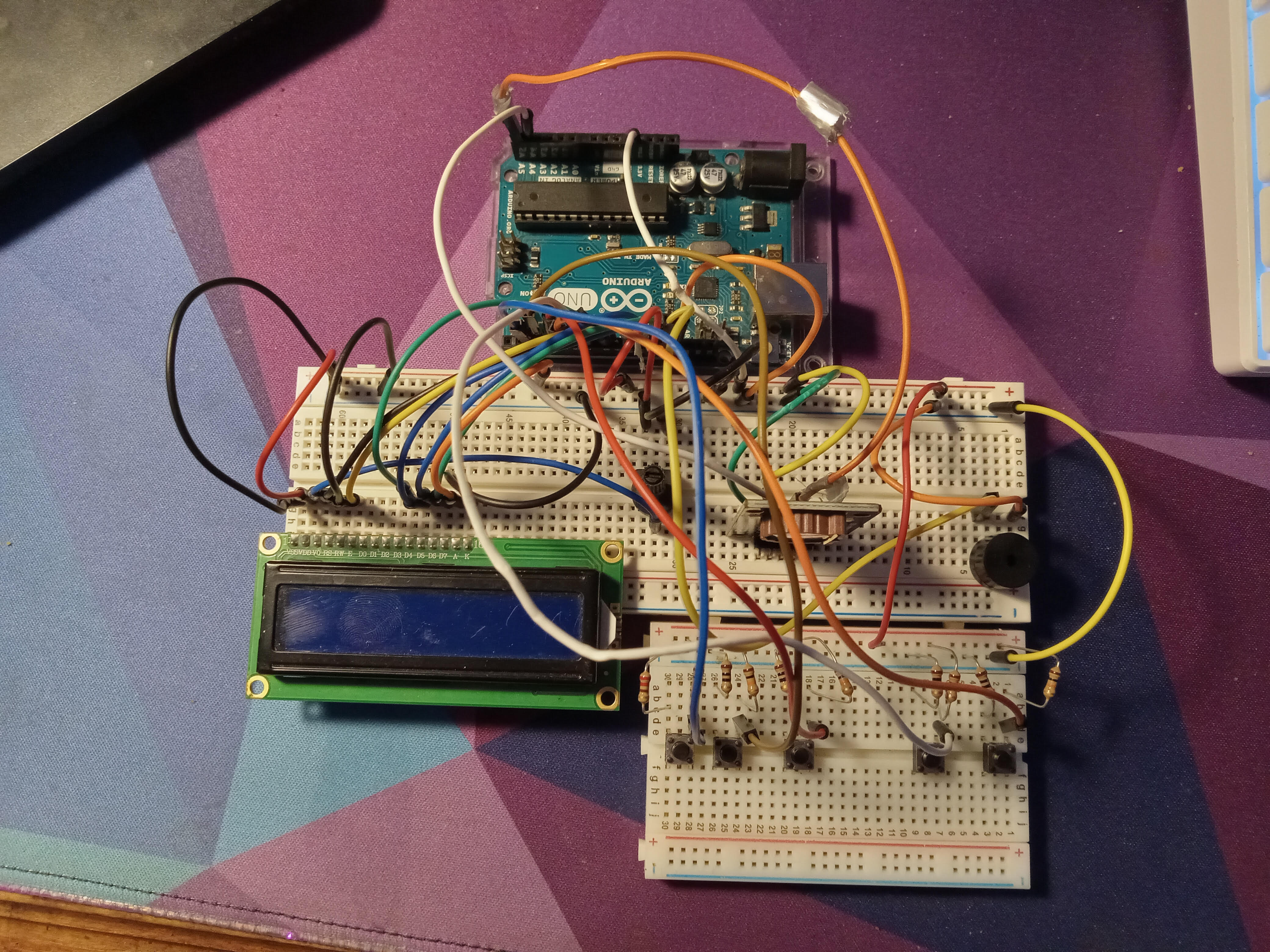
Arduino Alarm Clock
Arduino
Join
Official Arduino Discord - Discuss all things Arduino!
38,914
Members
View on Discord
Resources
ModelContextProtocol
ModelContextProtocol
MCP Server
Recent Announcements
Similar Threads
Was this page helpful?
Yes
No
© 2026 Hedgehog Software, LLC
Twitter
GitHub
Discord
System
Light
Dark
More
Communities
Docs
About
Terms
Privacy
Similar Threads
Arudino Alarm Clock
A
Arduino / project-showcase
9mo ago