esp8266 sketch stops working
wasn't really sure where to ask but my esp8266 has a sketch that creates a HomeKit device that controls a light strip which works fine,
but then sometimes when i power it on the sketch just seems to not work and i have to reupload the sketch for it to start working again.
any ideas?
tiny bit of info:
The light strip is RGB and connected to D2, D3, and D5 i think without looking and the esp8266 is powered through the 5v and gnd pins.
if you would like any other information to try and work out the problem let me know 😃
please ping if you have any ideas so i get a notification
16 Replies
it's likely a power issue... microcontroller boards are NOT meant to serve as power sources for components that have the potential to pull a lot of current (like motors, strings of LEDs, etc)...
👉 drop the number of active pixels to 4 & see if the problem goes away (that drops the potential load down to 240mA; considering each pixel can potentially pull 60mA each when lit at full brightness showing "white")...
🤓 pulling too much load is likely causing the ESP board to lose power to its microcontroller which is preventing it from doing what it's supposed to... (power cycling/disconnecting & reconnecting the power source should allow it to function properly as long as the strip stays unpowered or lowering brightness to 10% to reduce power consumption)
☝️ using a separate 5V power source with the ability to serve enough current to feed power to your strip directly (this way, your microcontroller board shouldn't be affected)...
This is my wiring if that helps
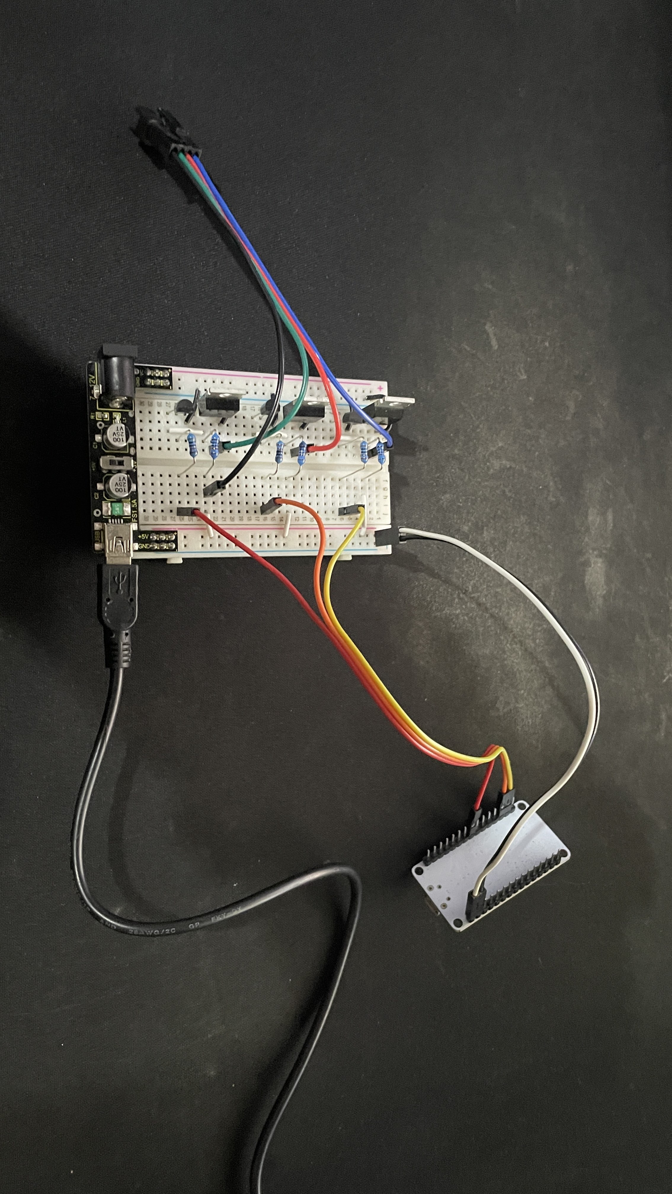
no it doesn't really...
btw, those breadboard power supplies can provide upto 700mA but that's only if you power it with a power supply that can handle more... since you're powering it via USB, it can only muster 500mA... and that's for both your microcontroller & your Neopixel matrix
https://www.kmart.com.au/wcsstore/Kmart/pdfs/43242870_Manual.pdf
this is also the manual for the light strip
So basically I should have a power supply going into that other side of the breadboard power supply instead
If it’s not getting enough current could that make the mosfets get a bit hotter than I think they should?
I guess just usb power isn’t able to power both the esp8266 and usb light strip
it will definitely overload the power supply's circuitry (typically the regulator)
🤔 it is interesting that the RGB display requires 2A so still much more than what your supply can provide... but now more manageable & you can set it to 25%...
⚠️ you cannot feed the 5V 2A power needed by the display on the same breadboard where that breadboard power supply is plugged into... doing so can damage both power sources...
So if I somehow limit the code to only 25% and in theory if I do some testing it hopefully shouldn’t have that problem?
it's all a matter of current.
as Toph mentioned that breadboard supply can't deliver 2A and the breadboard isn't designed to pass much current either. if you ALWAYS keep the brightness down so you are only drawing a few hundred mA maximum you could do some tests.
If things start melting you'll know you are drawing too much current 😉
so to power both the light strip and esp8266 and obviously allowing the esp8266 to control the brightness, what sort of setup do you guys suggest i need
you can power the esp off the USB, it's only the LEDs that require high current
for the high current you could get a 5v / 2A or greater wall adapter
the esp and external power grounds (only) must be connected
so if the light strip was powered directly from a usb wall adapter it would be fine but because its going through the breadboard and breadboard power supply that doesnt take that much current and thats why im having those issues
the esp sends low power control signals to the gates of the mosfets
the mosfets provide control the much higher current to the LEDs
either the low current breadboard supply and / or the poor current capability of the breadboard will cause you trouble
it will be fine (& much better since as mentioned, having the power source for the display & the ESP board separate will allow your microcontroller to keep working) as long as the wall adapter is at least 2A as the product specification indicates
⚠️ (remember that many products claim that it can deliver a certain amount of power but can only provide 20% less or in some cases even lower so it will actually get overloaded & cause problems too) ...
🤓 naturally using MOSFETs to serve as electronic switches that the ESP can control to send signals to your display is a viable option though may not be necessary since the display shouldn't need a lot of current for its data lines (unless I'm making the wrong assumption & that's actually an individually controlled RGB LED panel ~so separate red, green, & blue wires ... which will require the MOSFETs as suggested)
☝️ if this is the case then this tutorial will show you how to wire it up (here it's using transistors)...
📚 https://randomnerdtutorials.com/esp32-esp8266-rgb-led-strip-web-server/
👇 here's an example using MOSFETs to do the same thing...
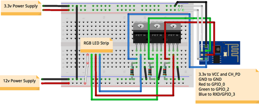
(these show 12V since many RGB LED strips out there are 12V but the principle is the same for a 5V one; ~another difference is common VCC like shown above or common ground RGB LED strips)
naturally, in both cases, the ratings of the transistor & MOSFET should match the power requirements for the display you'll be using...
correct its a seperate red, green, and blue wire with of course a 5v wire
so from the links diagrams, i can use one power source but obviously as long as it has enough current to power both light strip and esp8266
you could use 1 high current 5v power source, the esp will sip power from it, the LEDs will gulp from it