How do I write code by using datasheets and schematic?
As the question implies, I've come across that it's important to read datasheets and schematics, but from there, what do I do? I understand that it is supposed to help me in some way, but how do I apply that written information into code? I am a beginner:p
specifically, I'm looking at this schematic: https://content.arduino.cc/assets/SchematicNanoMotorCarriers.PDF
47 Replies
My question is more of a, "where do I go from here", and if there is any articles/videos/advice to watch/read I can get? Anything would be to great help:)
This is kinda a tough question.
I understand it's a tough ask 😅
Have you blinked an led?
Or maybe wired up a button?
Through my courses at uni, I've used matlab and simulink to program a simple differential robot, which chases a light source. But we've yet to learn code, as in C/C++/Python. So I'm taking this vacation as an advantage to start learning how to code on my own.
Well right now I'm family trying to break down how to apply code to a device in my examples buttons or leds as a basic bridge to build off of. So have you wired a button or led's before?
A button, no, led, yes.
Great. Moment
Ok so here is an schmatic.
Can you explain what it is telling you. In an over view?
https://images.app.goo.gl/2N2JmjNVM2ewjWCh9
www.google.com
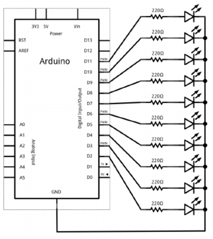
Circuit diagram of the ten LEDs array connected to the Arduino ...
Found on Google from researchgate.net
If I'm not mistaken, at location D2 to D11 led diodes have a resistor, which they are then connected in parallel, sharing same ground.
Can you see the image?
This?
Yes.
Ok so say we waned to make the leds strob top to bottom can you understand how you would code them?
psudocode:
for diode d11 to d2 {
diode HIGH
delay some amount of ms
diode LOW
delay -||-
}
Something like this?
for (int i = 11; i > 1; i--)
{
digitalWrite(i, HIGH);
delay(500);
digitalWrite(i, LOW);
delay(500);
}
Yup you got it simple rigyt?
sure!
So practically, it's the same, for "any" other schematic, I assume?
Yes now look at the one you shared it has a socker for a nano. And all of the pins for the nano are labeled a1,a2,a3,..... see it ?
yes!
Ok let's look at one pin just foe an example.
Are we talking A1?
Let's look at arduino pin D5 at the end of the line it has a fla called IN_M1..
SOMETHING LIKE THAT
I'm working from a phone. 🫣
I see it:)
Ok now find another line on the sheet with the exact flag.
In1_m4
ok, so the M4?
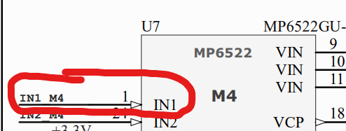
Yes see it says mp6522 on the top of that box?
yes!
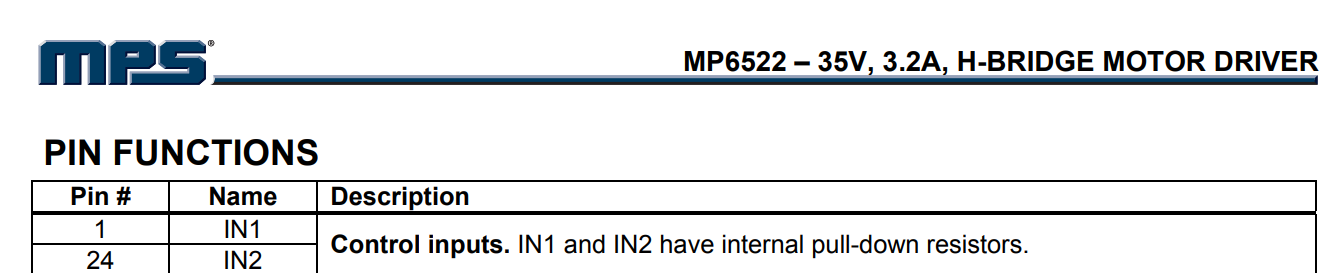
Ok so now you know nano pin D5 is conected to the IN1 pin on the mp5622 ic.. what is that ic? No clue. So you would then look up the data sheet and research what that chip does how it works what that pin does IN1 and what data is expected on that pin like on of? Or maybe that pin is sending data to the arduino. 😶 or maybe its a sync pin
Or a speed pin or... you get the idea.
Now depending on the person makinging the schmatic will be the naming factor of the tags..
My way is i always go with FROM.. TO.. convention so if chip a is sending data TO chip B. THEN Chip A pin will be listed first in the tag name and chip b pin name will be listed seccond..
But this is totally up to the board designer.
So does this help you?@IsakS
It's beyond helpfull!
when you wrote mp6522 ic, what is ic?
I also figured out that Pin1 IN1 is a control input, on the mp6522.
I figured it out, it's integrated circuit:p
Right. I know what it was irl and what that pin did.
My example is ifi was new and diddent know how would I prociede.
So In practice, what we figured out is that on pin 5 at the arduino, I can controll the motor at M1.
If you ever deal with me on the server if your wanting to learn. My main goal is to get you the process and tools so you can learn on your own.
Not just to tell you the answer. It's frustrating at times I know. But it makes a stronger community. And it makes the op a stronger user, and normaly they get the nice Lil dopamine hits from learning on there own.
I swear, you've made me get that feeling of unlocking my brain! I am beyond happy, to what do I owe. Thank you so much!:D
Just pass it forward and be active in the server as much as you can every can contribute at some level.
Again, thank you so much, you have no idea how much this means to me. I was so lost!
Your welcome. I'm going into a meeting but work at it as best as you can and tonight/tomorrow it you have more follow up questions some one can assist most likely.
I took some time to write in obsidian, and converted it to PDF, although the PDF document is not perfect, this should grasp what we've discussed. the text is very simple! And please do correct if anything is wrong! I did have to get some help writing the code from chat, but it sounds right.
@Maderdash
Thats why I like that copper connections on circuit boards are called "traces" because when looking at a schematic, its like an advanced adult connect-the-dots activity book. Instead of dots you have labels, buses etc. Its then your job to "trace" the connection from one end to the other and find out why its done that way. At the end of the day its just wires, and every wire has a purpose.
Sometimes schematics look like the image on the right ......... and more often than they should, they also can look like the image on the left.
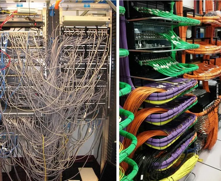
Hey! Who let you in my server room! 🙂
@AnonEngineeringerr left or right picture
left 🙂
@IsakS looked over the pdf.
Excellent notes. And great overview of this threads content. The only foot not i would add is the nameing convention FROM_TO is old pro standard. If this diagram was made by an amateur or a new ee they might i vert it. Or just call it bananna1.
So its a good idea to SCAN the tags names to see if you can identify there nameing convention.
😉
FYI i wish I could use you as an example of how to take note and apply ingested info.
something else to note is that microcontrollers themselves also have datasheets, just like any other IC.
There's where you'll find information about hardware inside the microcontroller that might make something significantly easier than doing it "manually" in code.
Some examples are timer peripherals for doing things regularly without needing to count cycles or resort to assembly, interrupt hardware for doing things "on reaction" to an external input, communication hardware for talking SPI/I2C/CAN/UART, DMA hardware for copying large blocks of memory quickly and in-the-background, to name a few.
If you're programming at the Arduino level of things like
digitalWrite, then the details that the datasheet has will usually go further than you'll need, but the general idea of "oh, I need to configure X peripheral before I do Y with it, and it needs Z information to configure it" will still help you understand how to use the libraries and examples that use said hardware; you'll know the general shape of the code you need to write
@IsakS I know this is a bit of a necro-post for a few-days-old already-answered question, but this might also point you to something you weren't aware of
A good example datasheet is the Atmega328P's datasheet; it's the datasheet for the microcontroller in an Uno/Nano.
Here's also where you get electrical information like max current per digital pin and power usage of the chipAND some data sheets have application notes, even example code or pseudo code, and show you other ways to use the device.