Schottky Issues: how does it work?
Hey All.
I need some help due to my lack of understanding.
I am planing a power supply für my esp32 devkit project.
Therefor I have a breakout usb-c power board and plan to secure it with a schottky diode, in case i plugin the usb into my esp.
but, and that is the question: is it normal to find like 0.9v behind the barrier?
i read a bit of the function of schottkys and all i found was:
if 5v comes in, after the diode barrier should be around 0.4v.
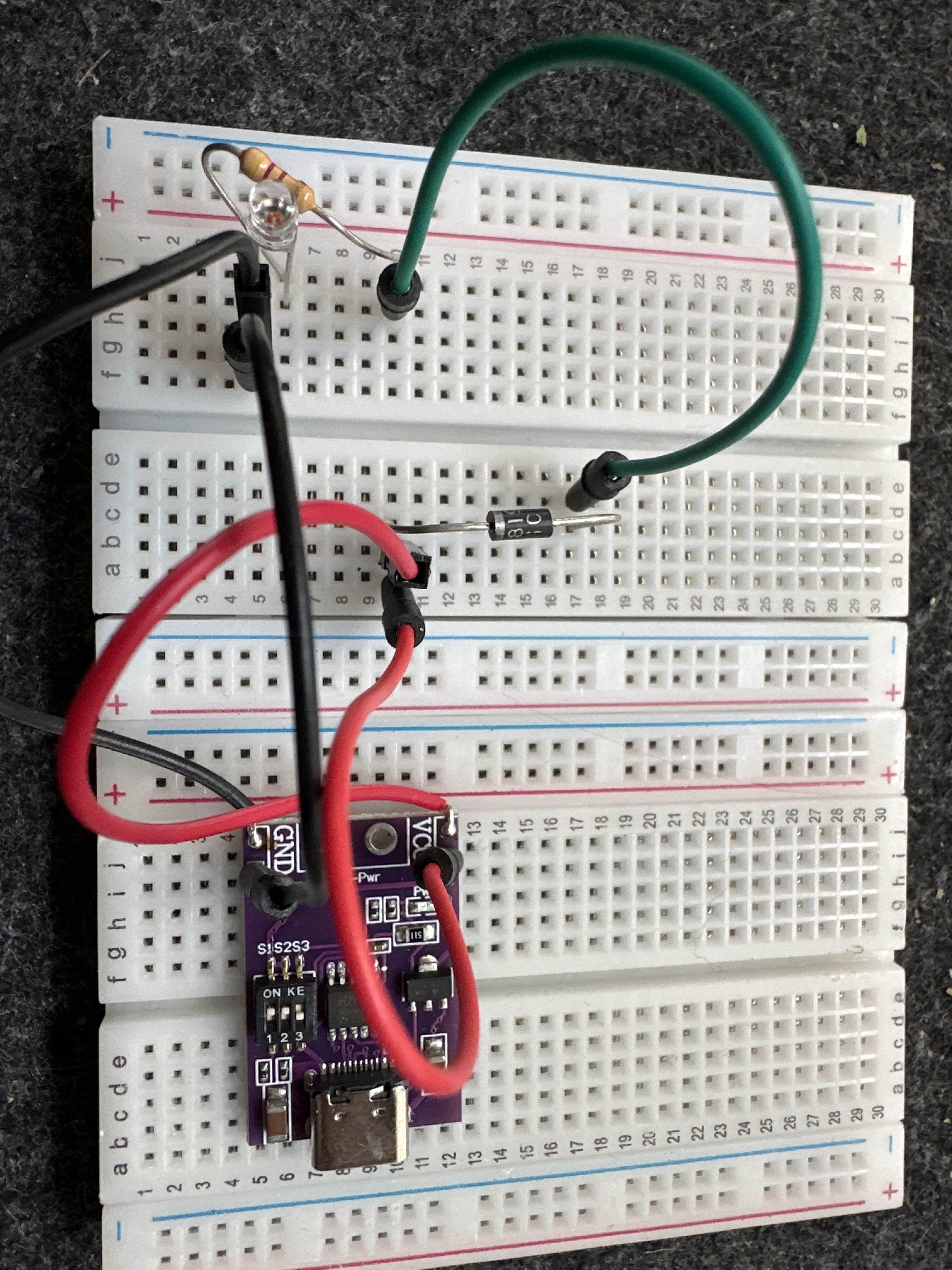
on the photo you see my test build of tryout component.
USB-C Breakout > 5v > 1N5819 > 0.9V > Widerstand > LED > GND
I tried several 1N5819 and also an SB160.
So, did I get the data wrong and should is the 0.9 not a fault?
5 Replies
Schottky diodes have a lot of reverse leakage current. The forward voltage of the LED is not met, so current cannot flow. You should see a lesser voltage with just a resistor instead of an LED.
Need to ask: so i just drop the led of the Testsetup? So that Only the resistor is Consumer?
Yes, just as a demonstration that the voltage on the anode side will be lower because the reverse leakage current is going to ground.
Ah thanks a lot. That did it. I would like to dive deeper into my issue: my current plan will look something like this:
USB-C Break-Out - | - - Supply Board - - LED RING / UltraSonic / Microphone
|
| - - Diode >| - - ESP-32
Everything on shared GND. USB-C goes VIN to the ESP by Pin. The other hardware has its VIN via a soldered breadboard with connectors. The Idea is to prevent the ESP to Power into the USB-C Board if connected via USB for development.
But currently i m thinking if i should build in a switch as i only prevent current vom esp zu the breakout but not the other way around.
Opinions?
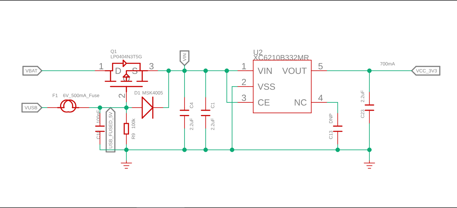
Most dev kits with dual power sources I have seen use a MOSFET for this. Here is an example.