How to connect 5v digital signal to ESP32 GPIO (3.3v) pin
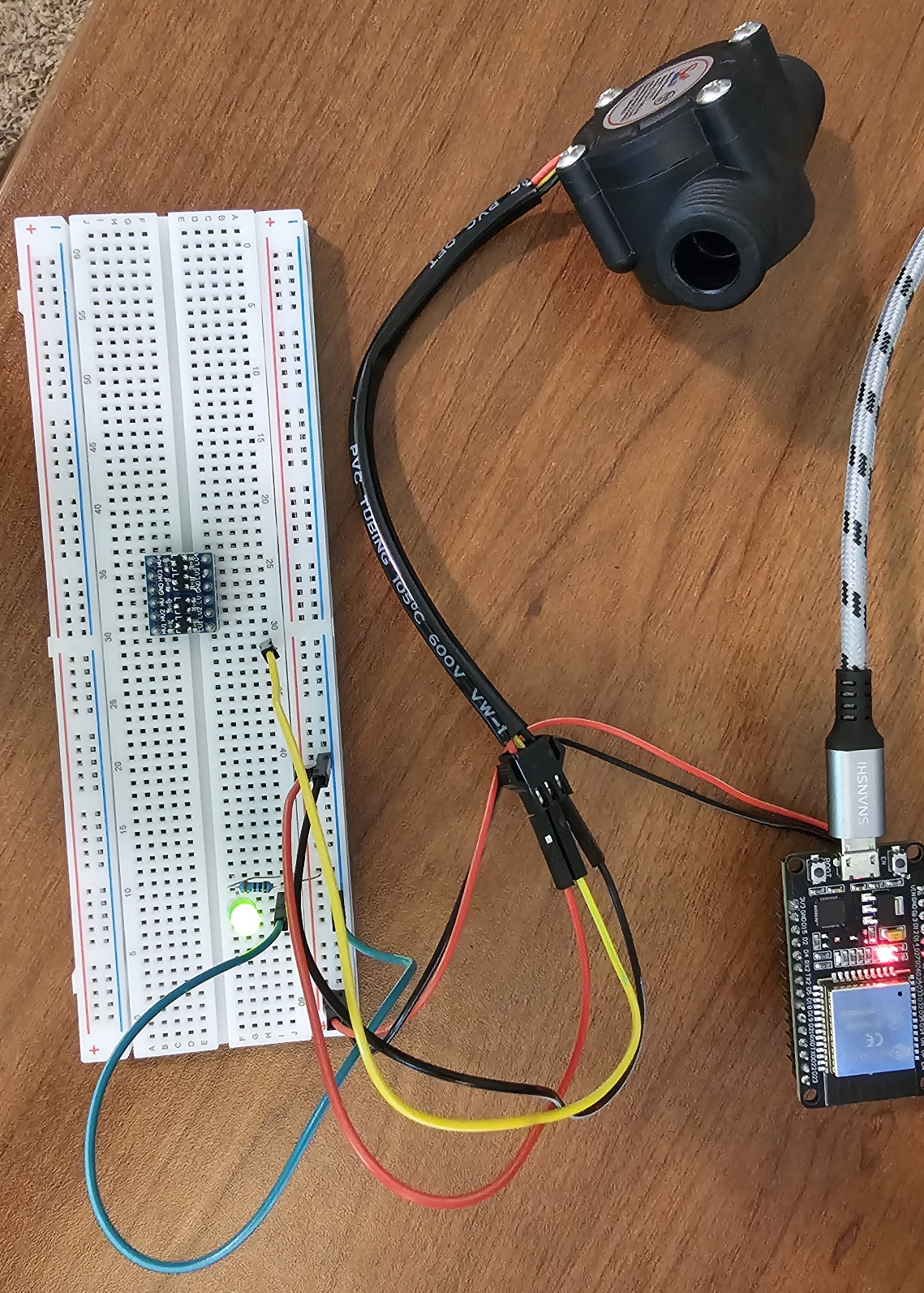
Complete beginner here. I have an ESP32 dev board, powered by a MicroUSB cable, connected to a breadboard. I also have a YF-S201 Hall Effect Flow sensor, powered by 5v and outputs digital pulses that correspond to flow, also at 5v. I understand that the ESP32 needs 3.3v inputs. How do I go about doing this?
I am currently powering the sensor using the VIN/GND pins off the ESP32 board. Google badly wants me to use a logic-level shifter, which I purchased. However, when I wired it up as Google suggests, it clearly messes something up with the board. I am feeling overwhelmed and frustrated and just need someone to point me in the right direction! Thank you!
It is possible I fried either the logic level shifter or the YF-S201. When I started, I could get variable voltage off the signal wire by blowing through the valve. Not so much anymore... Or was I seeing ghost voltage? Can I read digital pulses with a multimeter? I have so many questions