Stepper Motor Randomly Changing Directions
I am using an ESP32, ULN2003, and a 28BYJ-48 Stepper Motor. I have it set up so if the left button is pressed then it will go reverse, if the right one pressed it will go forward (also if any of the two previous cases, the blue led turns on) and if neither are/aren't pressed it stays still. For some reason it just changes directions whenever it likes. This is my code:
Thank you very much for your help.
160 Replies
Pins 34 & 35 are input only, they don't support
INPUT_PULLUPHi Anon, I just rewrote it with the INPUT instead of INPUT_PULLUP, it kind of fixed it, what I mean by that around 70% of the time when you click the button it goes in the right direction and the other 30% it goes in the wrong direction.
if you use just
INPUT you need to wire it with an external resistor
the pin must be held HIGH or LOW, if you don't use a resistor the pin will float
can you use other pins? 34 - 39 are the special "input only" pinsCould I use Pin 25 and 26?
yes, they support
INPUT_PULLUP
when you use the pullup a resistor inside the chip is added for youWill the PULLUP make the input be default high?
When I ran it with the PULLUP no signal was ever sent to the ULN2003 Board
yes, the pin idles HIGH until you push the button, then the pin goes LOW
Using the PULLUP didn't work, the board didn't receive any signals (indicated by the RED LEDS), I tried PULLDOWN but it would only go in one direction on both buttons
did you set the pinMode back to
INPUT_PULLUP? I did, did I mess up anything else when doing that?
looks OK, put print statements in your
ifs to see if they are executing
and add Serial.begin(9600); in setup
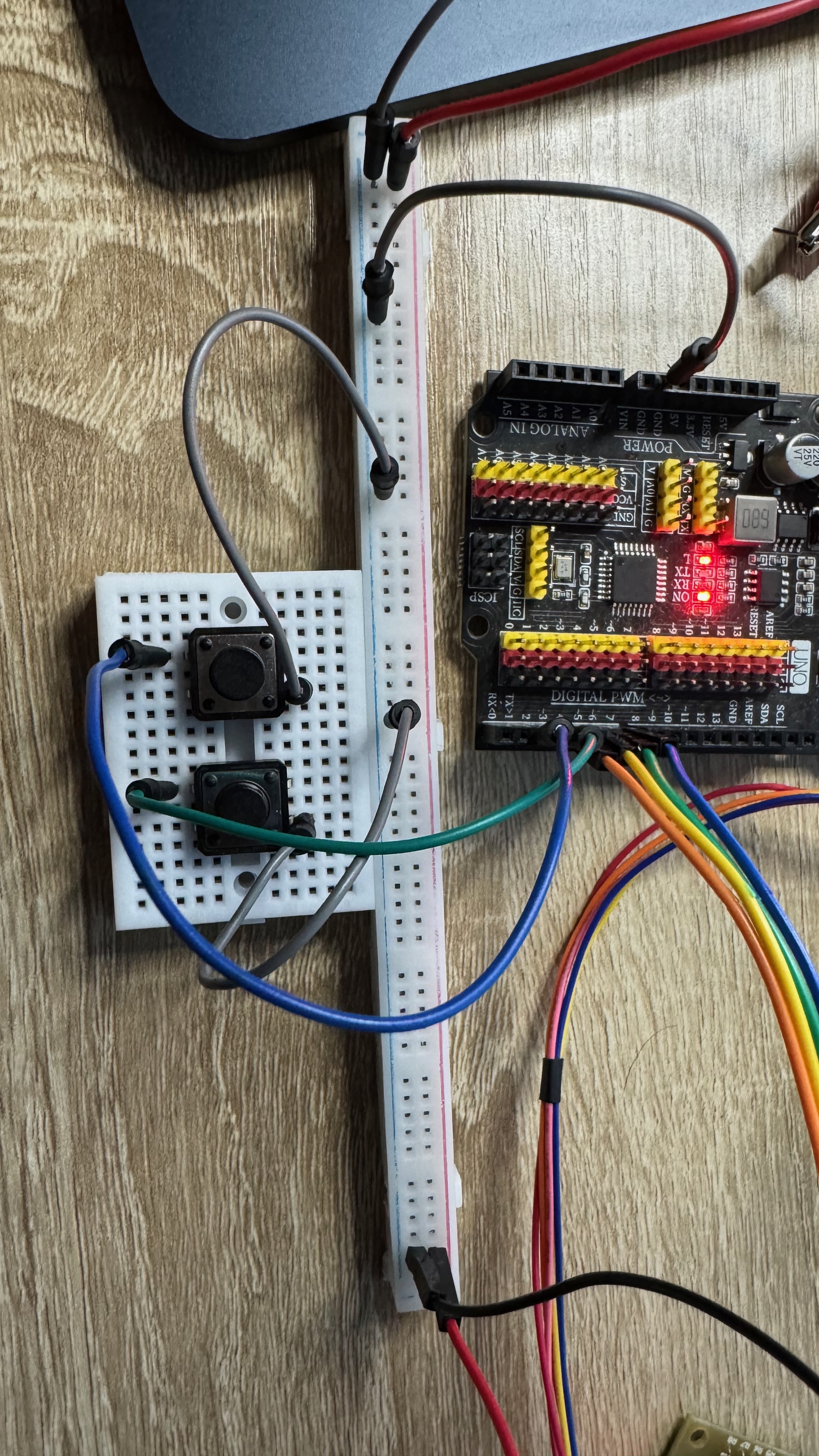
you have the other side of the buttons to ground right?I don't actually, nothing is connected to ground for the buttons
pin > one side of button, other side of button > ground
the pullup holds the pin HIGH (1), when you press the pin connects to ground (0)
I don't have it setup like that currently, it is outputting high on 33 and 32 which are connected to my button respectively, and then connected 26 and 25 with INPUT_PULLUP to the other side of the button, so when I press it 'bridges' the connection.
I will try to do it like you mentioned
no, just one pin per button
It works now!
Thank you!
pin 25 . one side of button, other side of button to ground
Regarding this, does this mean pins 33 and 32 are reduandant?
yes, you only use one pin per button
in this case 25 & 26
one for each
That is so much more simpler than what I was doing, thank you!
One more thing, Would there be any way to stop the motor from getting hot? I assume its because of the voltage still going through it
because of current flowing through it yes
are you using a 5v power supply for it?
Yes I am using a DC Power Supply
at 5v, iirc that is what 28BYJ-48 is rated for
I have it set to 5 volt and it is currently drawing 0.235 amps
so a bit over 1 watt is being dissipated by the motor
Would I be able to integrate a MOSFET in this system to control the voltage or ground that is connected to the ULN2003 board?
you could use a MOSFET as a power switch, another pin could drive the MOSFET to act as "motor on / off"
does it get really hot? it shouldn't
Not really hot, just warm
I was planning on using this control my blinds
warm is normal
Oh okay!
you can also use a drv8825 driver with a bigger stepper if you need to
This driver looks similar to the hw-134a drivers that I have
arduino doesn't support
printf, use Serial.print
those drivers have a STEP and a DIR pin, A4988, DRV, HW, all work about the same, just the specs are slightly differentCould I store this program on the ESP32? So I have it start this program anytime it boots up (not connected to computer)
once you upload it it stays on the esp until you load new code, even if power is removed
Oh, its that simple? Thank you!
thank Arduino / Espressiff 🙂
Thank you Arduino and Espressiff 🙂
lol
This is the code know, for some reason deleting the two lines that made pin 33 and 32 outputs broke it, so it is doing that 70% 30% thing again
Or it will go in the right direction in the begining then shake and go the wrong direction
shouldn't make any difference if it's all wired right
these lines weren't doing anything
brb
putting in a new stepper motor
didn't fix the issue
still got that 70% 30%
I deleted the Serial.Println for 1&1 and 0&0 and now it doesn't even spin the motor
I can feel the motor trying to rotate but it doesn't
oh, you had 32 & 33 as
OUTPUTs in your original, where are they going?instead of having the pins go to ground I used 32 and 33 as High signals and when a high signal was detected on 35 or 34 it would act accordingly
oh, then it should make no difference
That is also what I think
but know it won't even rotate.. , all I did was delete the Serial.print for the 0 & 0 and 1 & 1 cases
serial has no bearing either
i'll simulate, give me a few minutes
I think when I used control f it messed up the speed, I made it 10 now it works
looks like it should work...
https://wokwi.com/projects/435146748848937985
wokwi doesn't have your exact hardware, but the logic is sound...
What would you recommend doing?
i thought you said it's working for you
It is doing the 70% working and the 30% not working
the 30% is specifcally going in the wrong direction
different than the sim i linked?
yes
then i'd suspect wiring, that's your code
(and BTW, wokwi doesn't simulate current, you can't wire like i did in real life)
but it simulates the logic perfectly
what's pin 2 - the onboard LED?
Pin 2 is the onboard blue led
ok, not simulated
I was using it as a trouble shooting step, I can get rid of it
shouldn't be causing trouble...
I agree, but maybe for some incomprehensible reason
still doing it with this barebones code:
What's funny is I have been trying to do this project for about a year, and the same thing kept happening I didn't know where to go to find some help until I came across this discord like 3 hours ago
Maybe its cursed?
not sure what the problem is, doubt it's a curse, 95% of the time it's wiring or lack of sufficient current from your power supply 😉
I am using this to supply the motor:
Jesverty DC Power Supply Variable, 0-30V 0-10A Adjustable Switching...
Jesverty's SPS series is a high-efficiency, compact, lightweight, high-performance Switching mode DC regulated power supply. It can be used as a constant-voltage(C.V.) power supply and constant-current(C.C.) power supply. Also, convenient functions like a USB type-A charging port, and a high-prec...
that should be more than enough 🙂
is the power supply ground connected to the esp ground?
Yes I have common ground point
Should I take a photo of the wiring I have going?
see the faint grey lines inside the button here?

that represents how the button is wired, a press connects left to right
yes
I think I have that wired up correctly because it doesn't start the motor until I press the button
maybe the ULN2003 isn't happy with 3.3v logic, usually see them on Unos (which use 5v logic)
I can plug in an arduino uno one sec
yeah, just need to change the pin numbers
Also, I just want to say thank you for sticking around, I just want to learn this stuff better and it mean's a lot.
you're welcome


It has the same issue, it does the 70% working 30% not
that's good news, bad news
good news is the levels don't seem to be the issue
bad news is it still doesn't work...
here's mine btw https://wokwi.com/projects/435148961261584385
just as a style thing, name the pins up top so if you need to change them you only have one line to change
i don't see anything obvious wrong with the wiring...
😁, did it right the first time (LETS GO)
yes, now if you want an LED on pin 9, only one place to change
I should have done it this way the first time
live an learn 🙂 plus, it's pretty obvious what
Led_Pin is, 6 months from now yer like "What is pin 9???"
or worse, what does 9 mean here?not even 6 months, tmmr lol
not related, but here is a different way to deal with buttons
https://wokwi.com/projects/430668928277663745
it only looks for change, not is it pressed or not
I am going to save this for a controller I want to build, thank you!
but in your code, it isn't printing the button pressed correctly?
in your code it should print continuously while pressed
does it work differently if the stepper is unplugged?
(not ULN, just stepper)
the lines are correctly printing
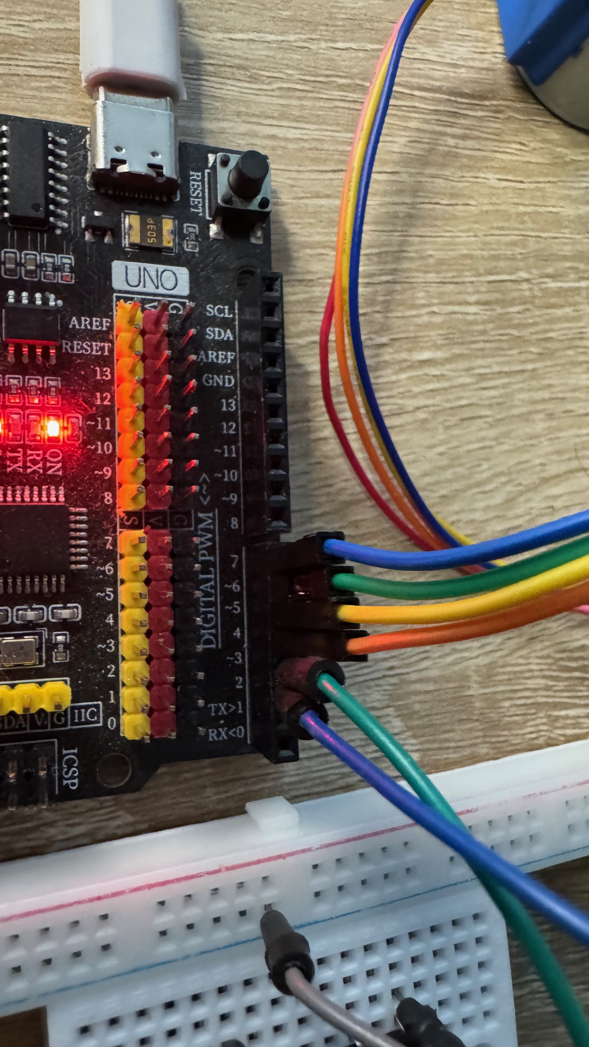
is this order correct?
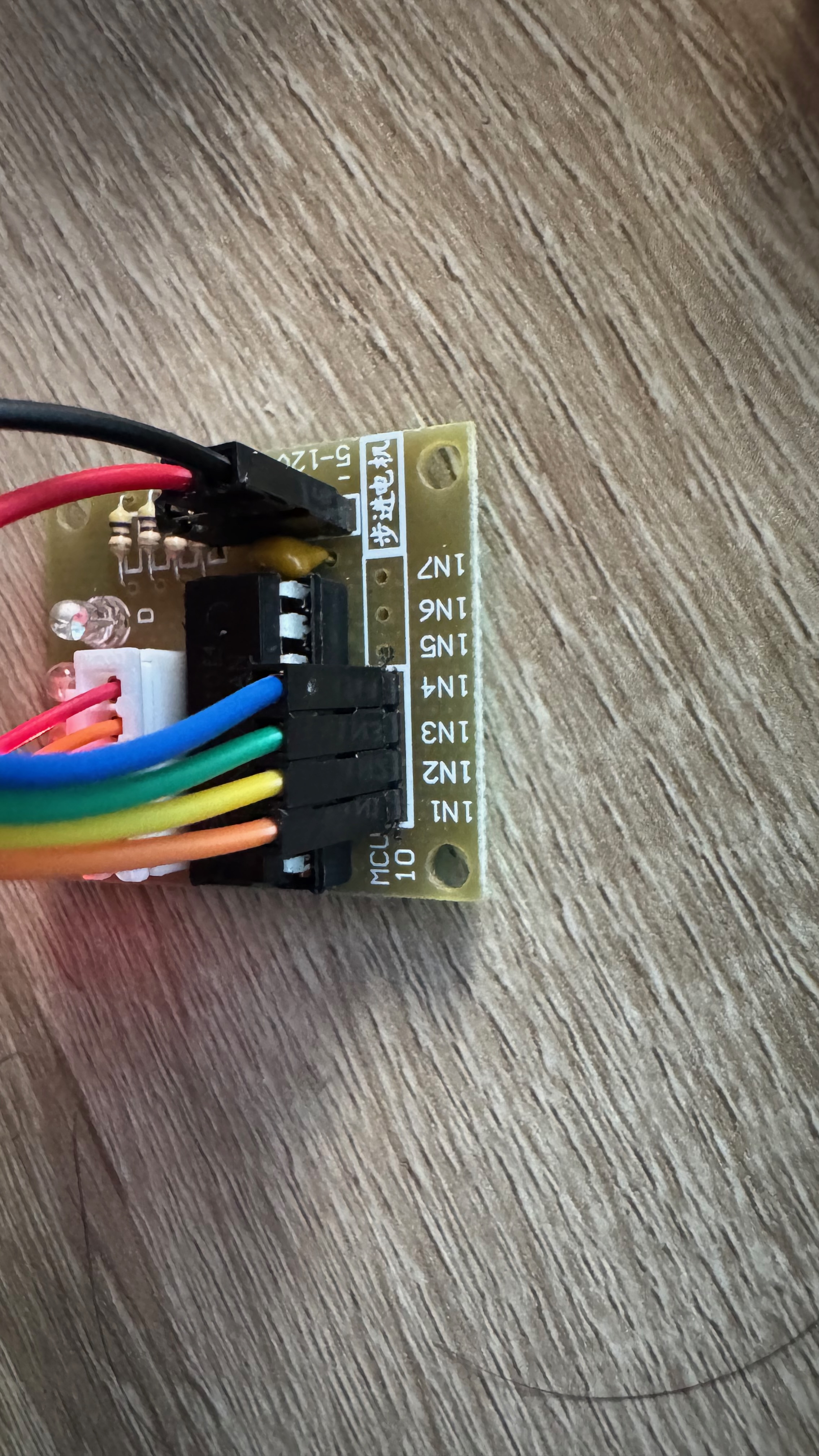
IN1 is connected to 4
IN2 is connected to 5
IN3 is connected to 6
IN4 is connected to 7
yes
so all is well, except the stepper moves erratically?
and sometimes incorrectly
the LEDs on the drivers are also erratic?
no
but I did notice that the 'C' light doesn't ever turn on
It hasn't turned at all
this ULN2003 is brand new
try replacing that wire
duponts fail more often than you'd imagine
and if all 4 don't light the stepper won't move correctly
I turned everything off, I started smelling burning
never a good sign
I have absolutely no idea what is burning
motor hot or the ULN chip?
nothing is hot
the motor is almost cool
just a little warm but its cooler than usual
smth should be warm if you smell burning
motor power is direct from supply, not Uno right?
correct
did current spike?
no normal current
I went and got a fire extingusher just in case
I turned everything back on
I don't smell burning
I have no idea
try the example here https://lastminuteengineers.com/28byj48-stepper-motor-arduino-tutorial/
The LED is still not on, for the ULN2003
yeah, that is definately a problem
Let me get another one, one sec
proper operation depends on those four signals driving the coils
Okay I went and got a new one, immediately the 'C' light turns on
does it work any better?
the stepper i mean
It only goes clockwise
try the example above
you can use your pins, just change the code
btw, this is formatted as a codeblock
yeah their code also doesn't work for me
it keeps going clockwise
just the code above?
Yes
that is the standard "known good" code, points to an issue with the ULNs or steppers
I just in a new ULN2003 and Stepper, samething
damn, so I have defective hardware 😭
hardware or wiring, the codes we've been playing with all checkout
touching the stepper motor, as the motor is starting it trys to turn anti clockwise but it changes direction to clockwise
Sultan_Servo_Uno - Wokwi ESP32, STM32, Arduino Simulator
Run IoT and embedded projects in your browser: ESP32, STM32, Arduino, Pi Pico, and more. No installation required!
that's the example, just the pins changed
they have this code on the amazon page:
ELEGOO 5 Sets 28BYJ-48 ULN2003 5V Stepper Motor + ULN2003 Driver Bo...
ELEGOO Inc. is a professional manufacturer and exporter that is concerned with the design, development production and marketing of arduino, 3d printers, raspberry pi and STM32.
Our Dream is to make the best price and best quality produce for customers.
So we would like to receive your valua...
wait, why does that code work???
Amazon code - i have a bridge in Brooklyn to sell ya 🙂
it turns anti clockwise and clockwise now?
lol
But that code actually works for some insane reason
but that works?!?!
It does!?!?!
It is also really efficent
the motor is cool to the touch
I don't understand it
beats me, that code doesn't work in the sim 🙂
why does it WORKKKKKK??!?!?!?
just back to earlier, they used
define to name the pins
is #define or const int better?
that starts an argument every time 🙂 I prefer the
constant but...okay then I will stick with the const int
so it would seem that driver wants a different pin order
🫠
so try that order with your code
Sorry, I am not understanding it
Would you mind explaning what you mean?
brrb
your code had
that is the order of IN1 - IN4, it looks like they want the reverse
what does that do?
I think it works correctly
i've never seen a driver that wants reverse - but the "right" order is imperative
(also never seen code on Amazon that works 🙂 )
It works know! Thank you so very much, I never would have figured this out by myself, you truly are a great person, staying with me for 4 hours, thank you very much!
at least we got somewhere 😉
glad it works, now that you know the right setup for your hardware you can experiment with code
Yes, I want to hook it up to the internet and then have alexa control it, without using esphome on home assistant
so next step is get it working back on your esp
Definitely, but that is probably a tmmr problem, I have been trying to figure this out sense 10AM, its almost 8:30PM over here
not gonna tell the wife about this project - she'll want me to build it for her 🙂
lmao, my dad would make me do this for the whole house
yeah 11:30 here in the east, and work tomorrow
Wow man, up until 11:30 for a random stranger, I don't know what to say, thank you so much
oh it's better than binge watching TV, no worries
I was thinking of going to binge right now, after getting some food of course. Alright man, thank you very much again, and I hope you have a great rest of your night!
you too!