Arduino Project: RFID
Hello everyone my name is Fang and I've been trying to ask to work on this project for about 2-3 days now but still haven't figure it out. The goal for this project is have it where it can read the card ID in console so I can know which card ID is which. I'm having trouble trying to figure this out but still haven't gotten a solution to what this problem might be. I've tried resources from books and youtube videos which will be below this paragraphs but I still haven't uncover what the issue was.
If there is a way I can resolve this issue or if someone helps in this situation then that'll be good to but other than that I was wondering if anyone know what I'm doing wrong in order for me to continue having failure after failure.
150 Replies
Code from example:
Video reference:
1. https://youtu.be/cFK87MJ96A8?si=ykUX-NgMiq9qIhti
2. https://youtube.com/shorts/YEcnFiB_6XM?si=T0GZOIAL9o9uB8FD
DIY Engineers
YouTube
Arduino RFID Module RC522 - How to Use
In this video we'll go over how to use the Arduino RFID Module RC522. We’ll go over basics, module pins, how to connect to Arduino, programming in Arduino IDE, and testing. The main focus will be around reading an RFID tag’s UID (Unique ID).
Related Blog Post: https://www.diyengineers.com/2021/04/15/learn-how-to-read-an-rfid-tag-with-rc522-...
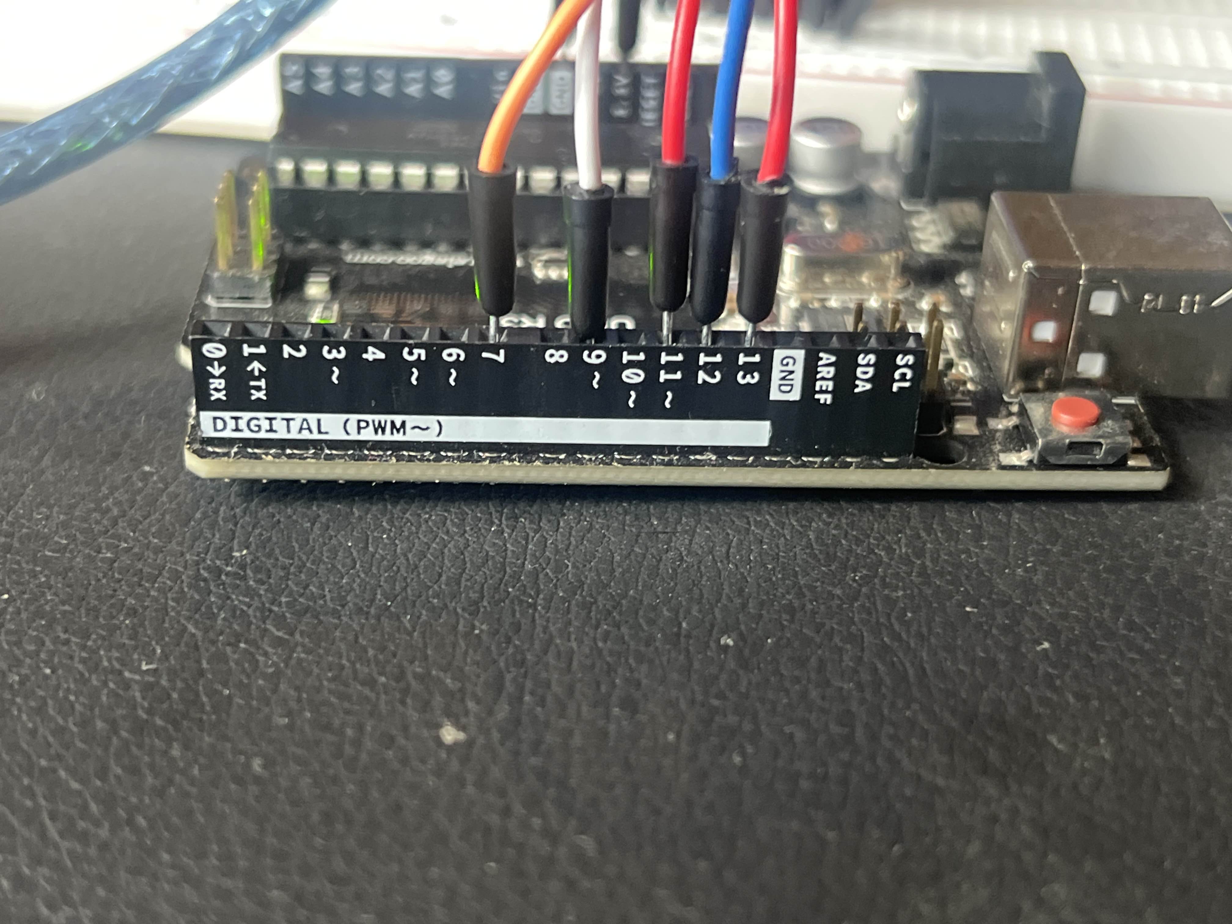
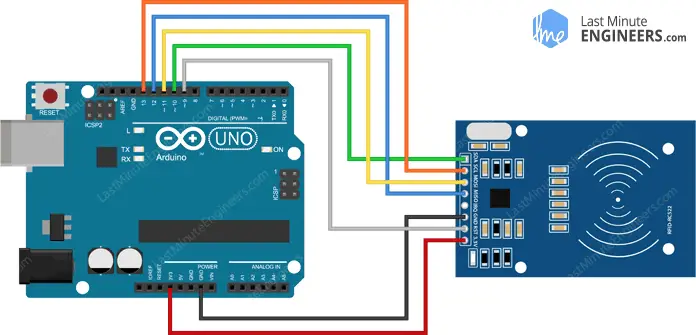
Wiring
Power Input to 1.3v
Reset to 7
GND: to GND
MISO to -12
MOSI to -11
SCK to 13
SRA to -10
Good that you included the video
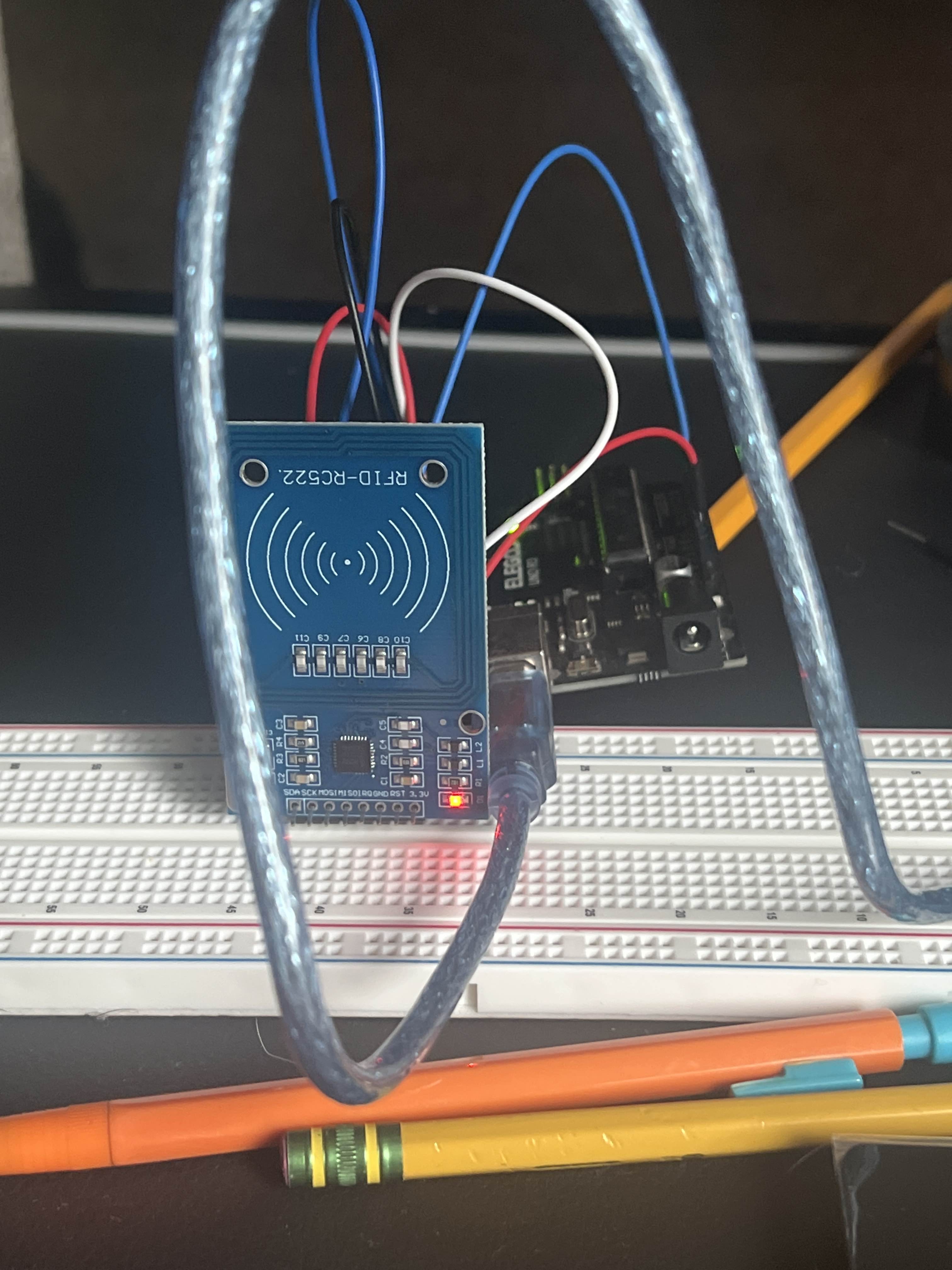
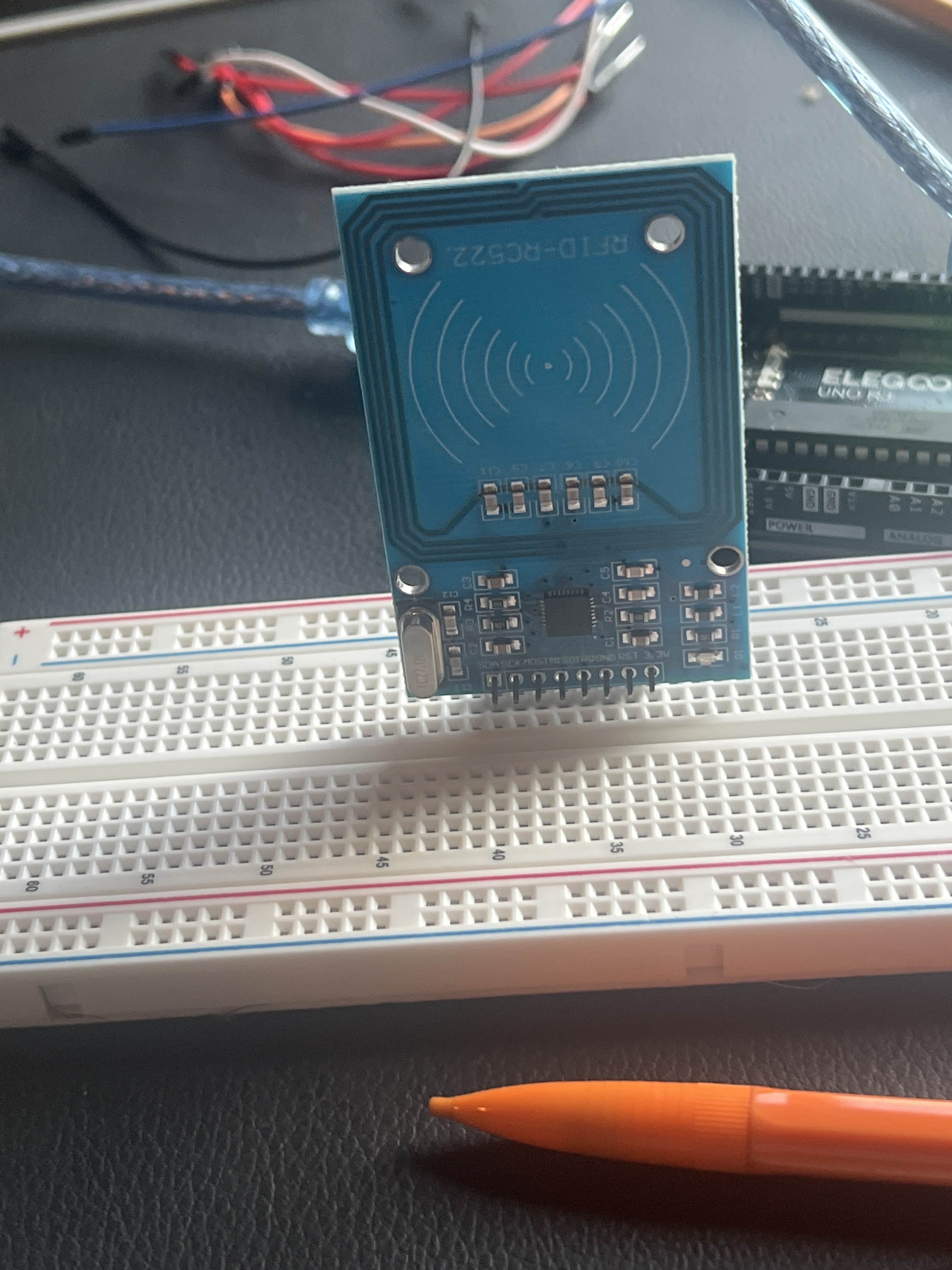
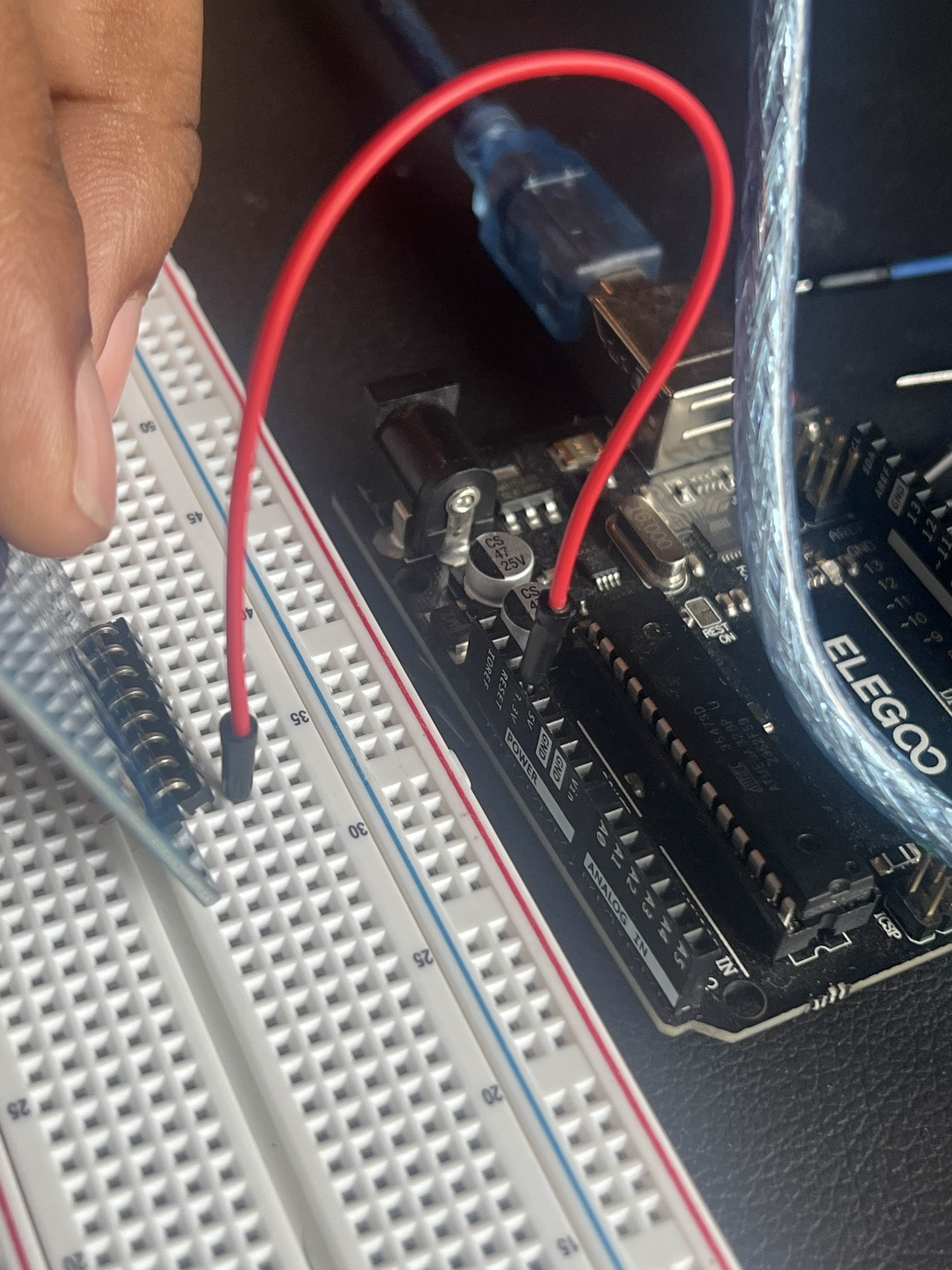
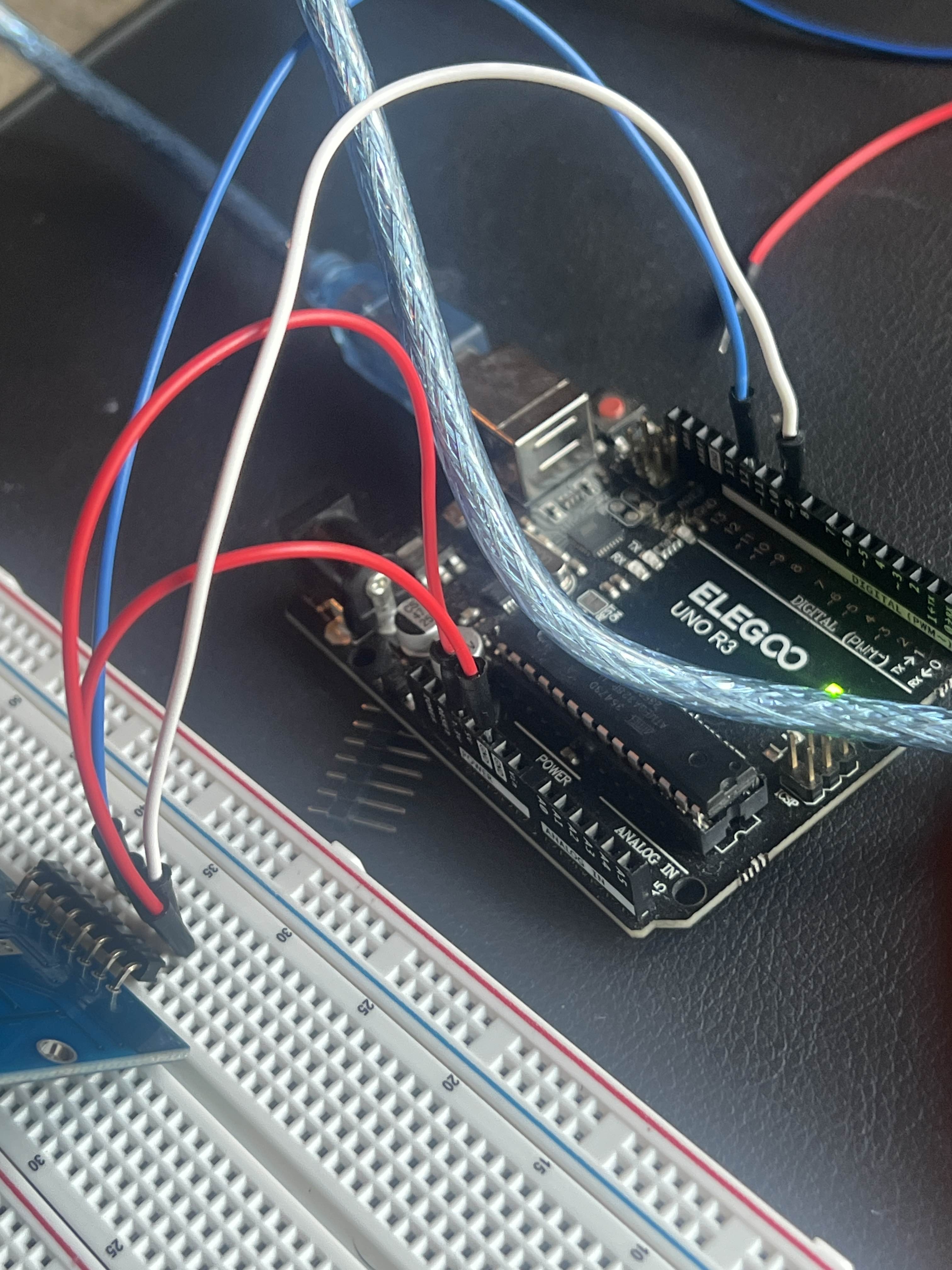
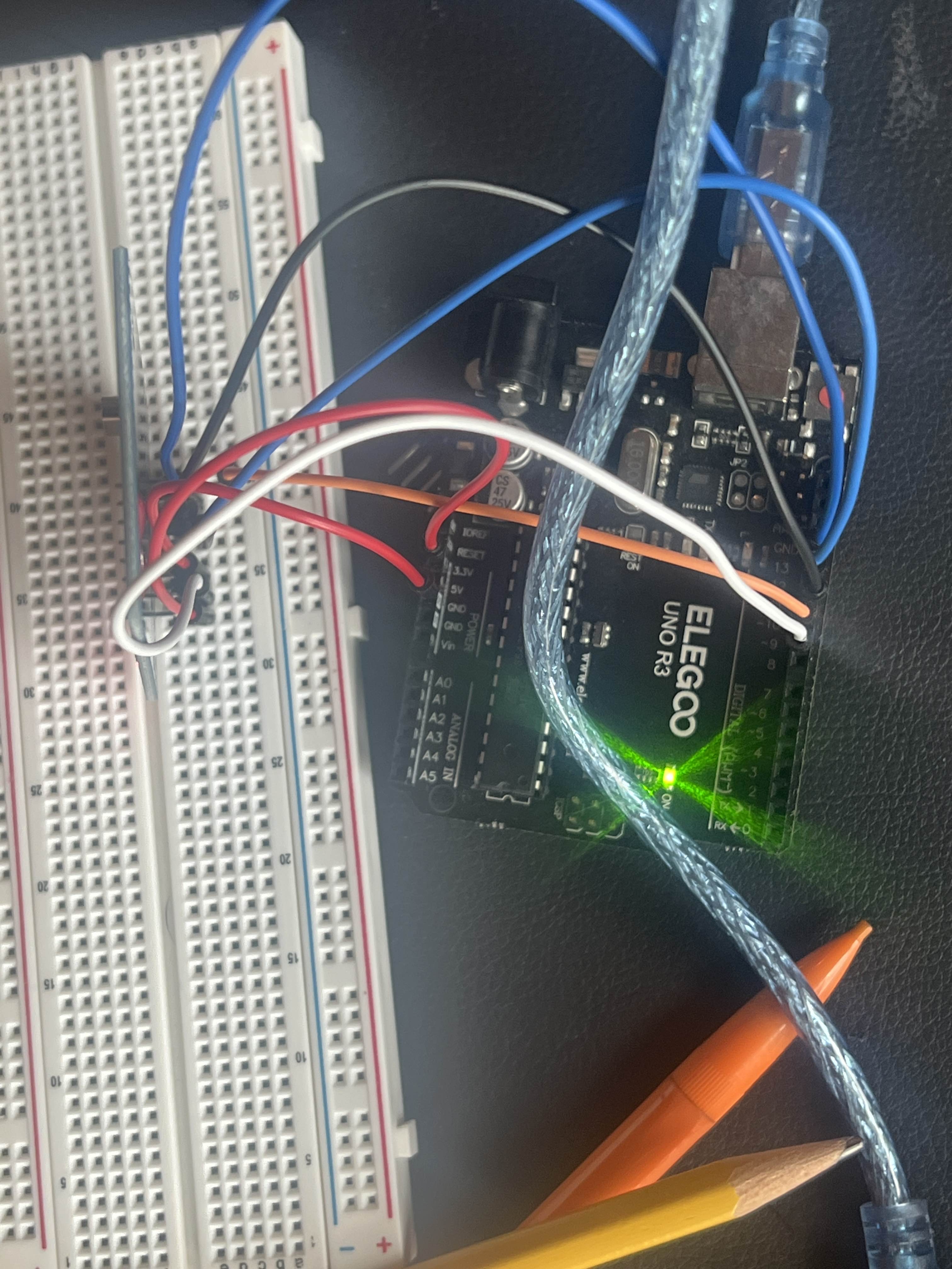
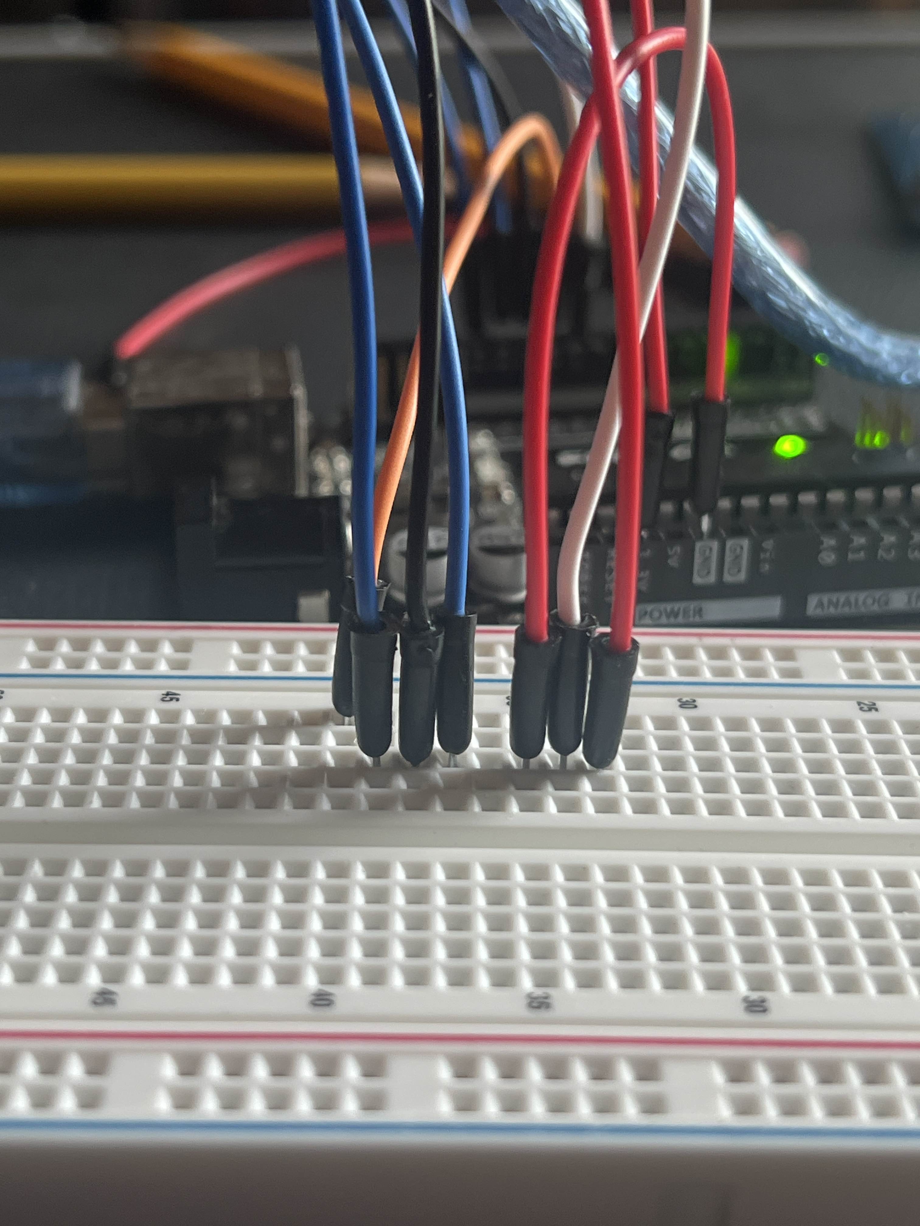
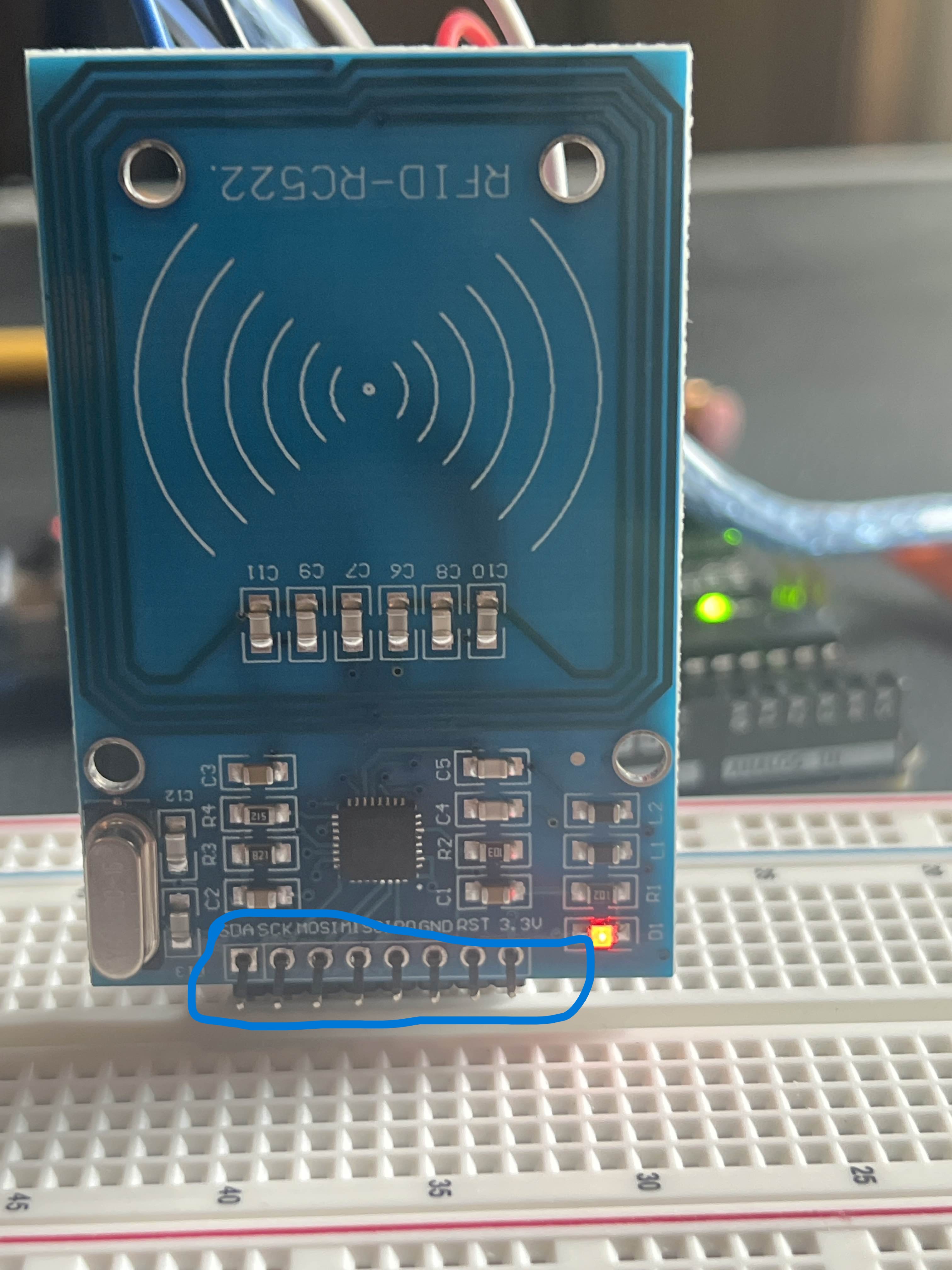
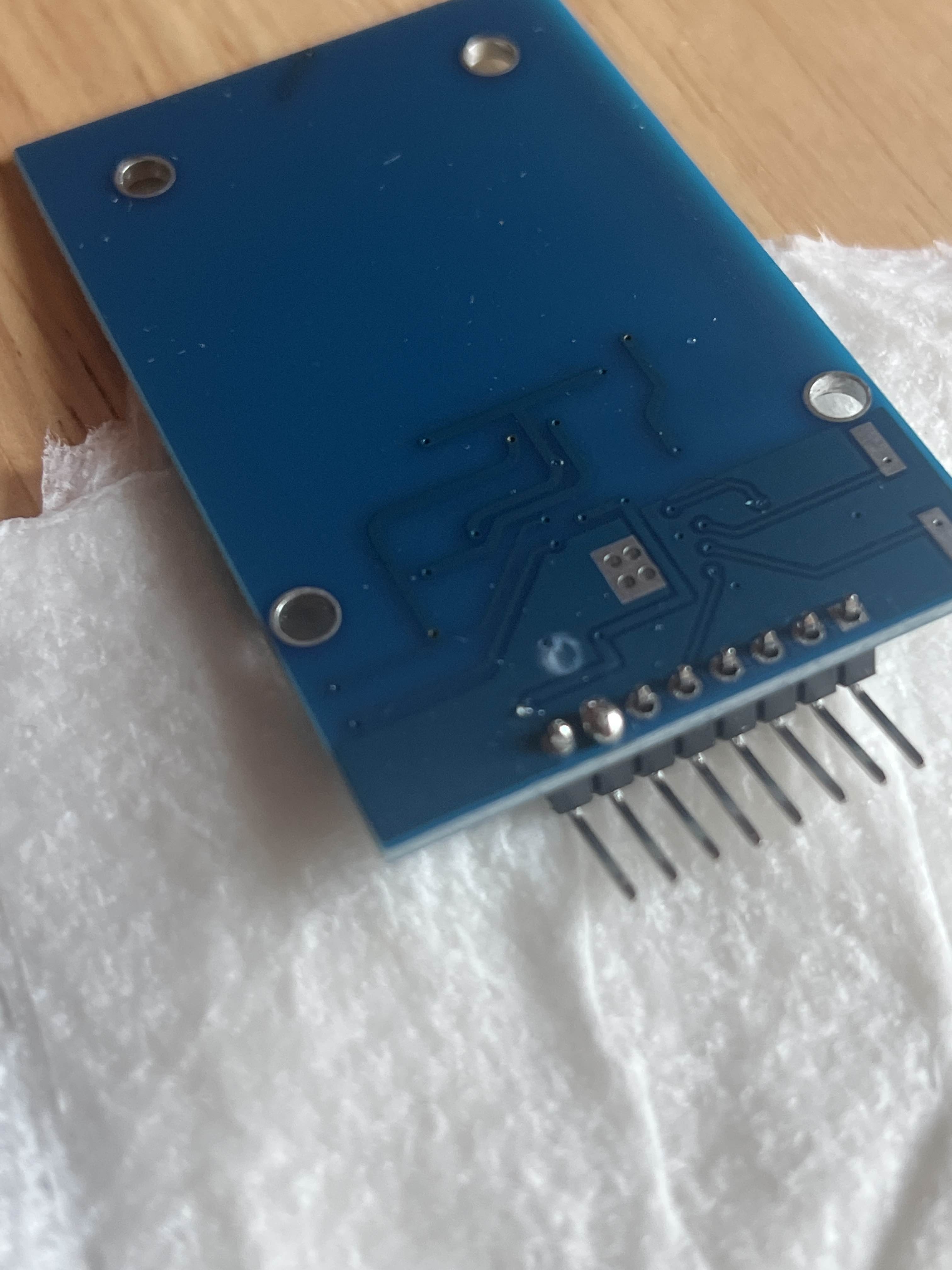
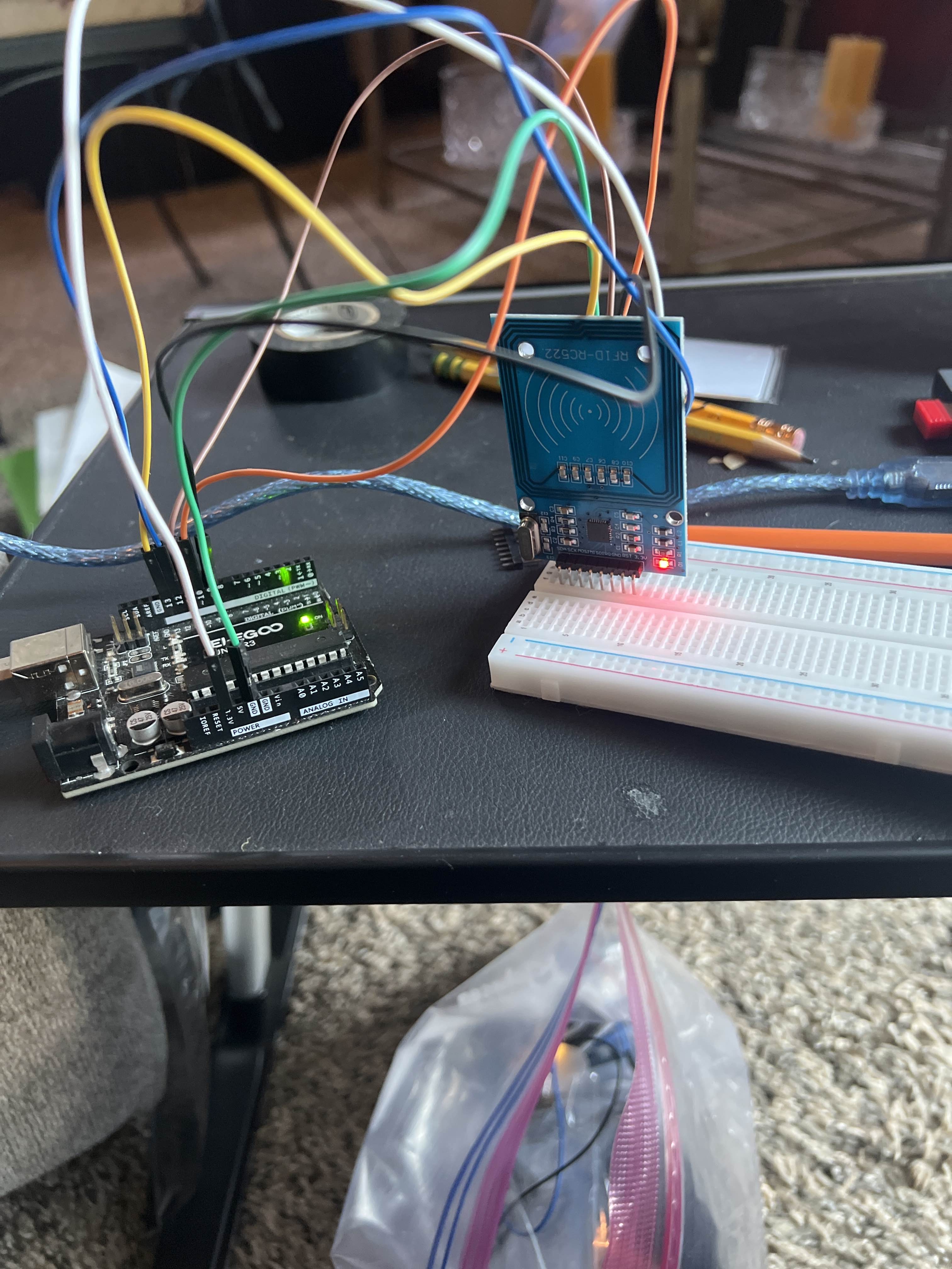
Photo proof
Front
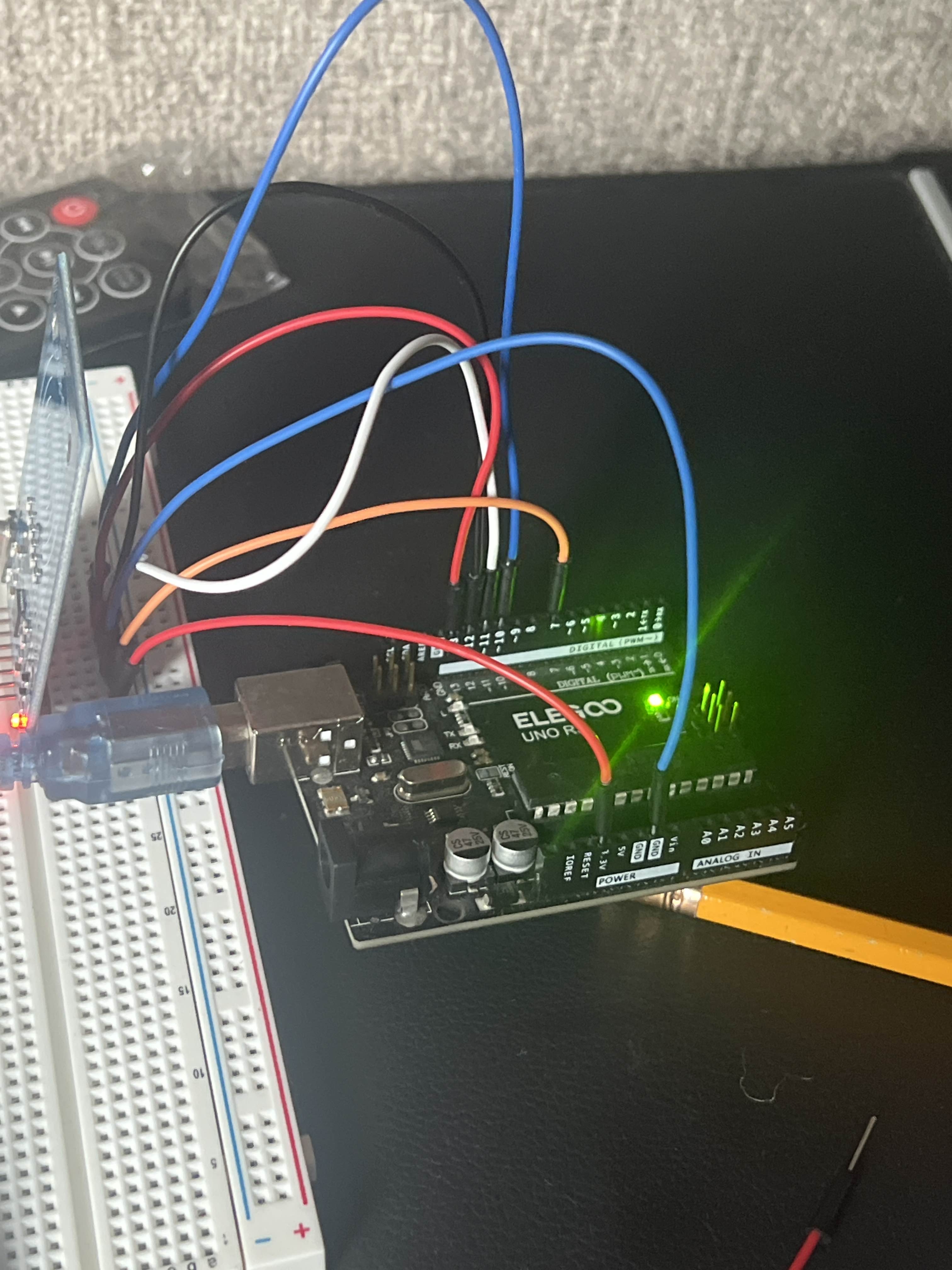
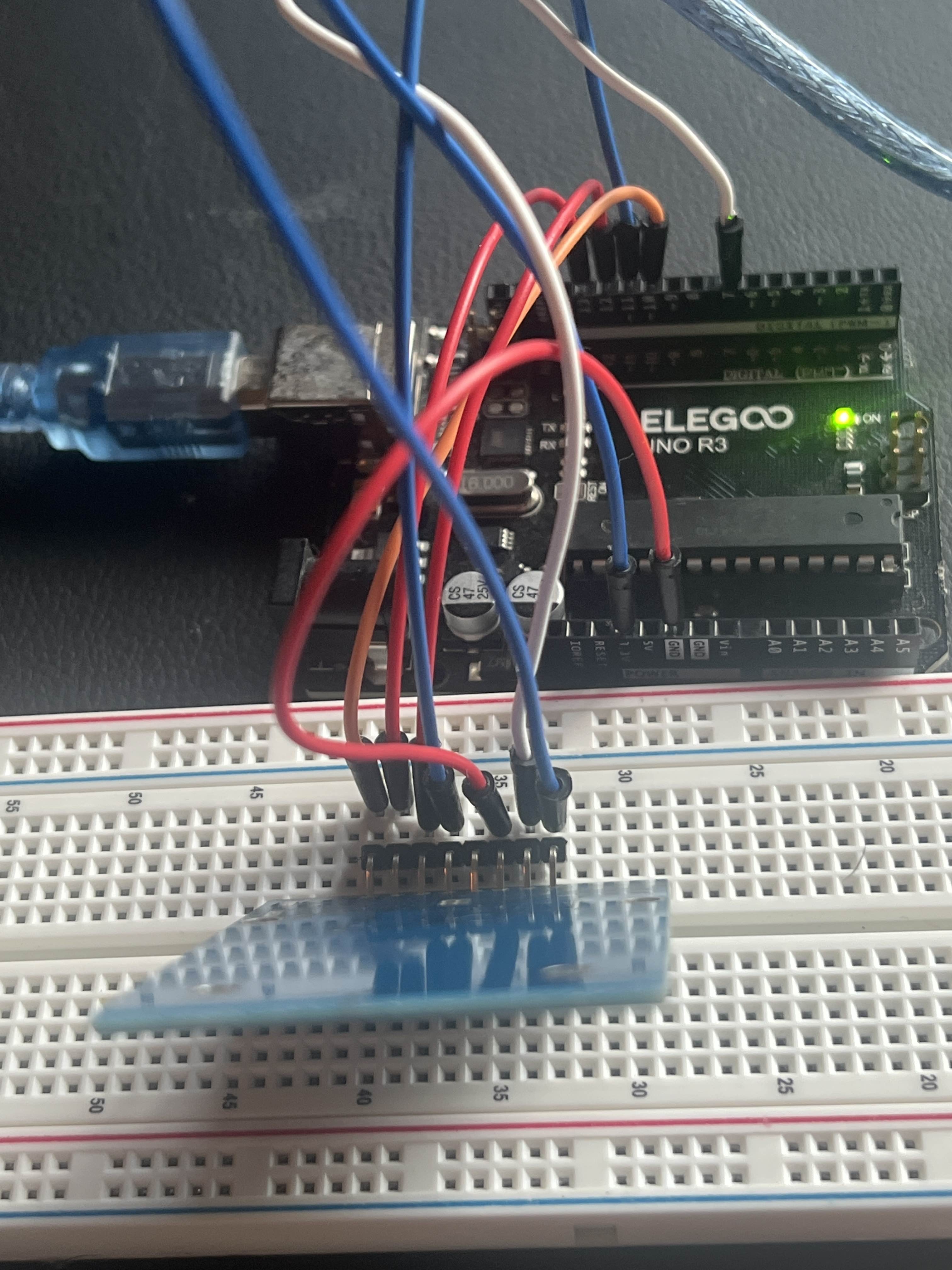
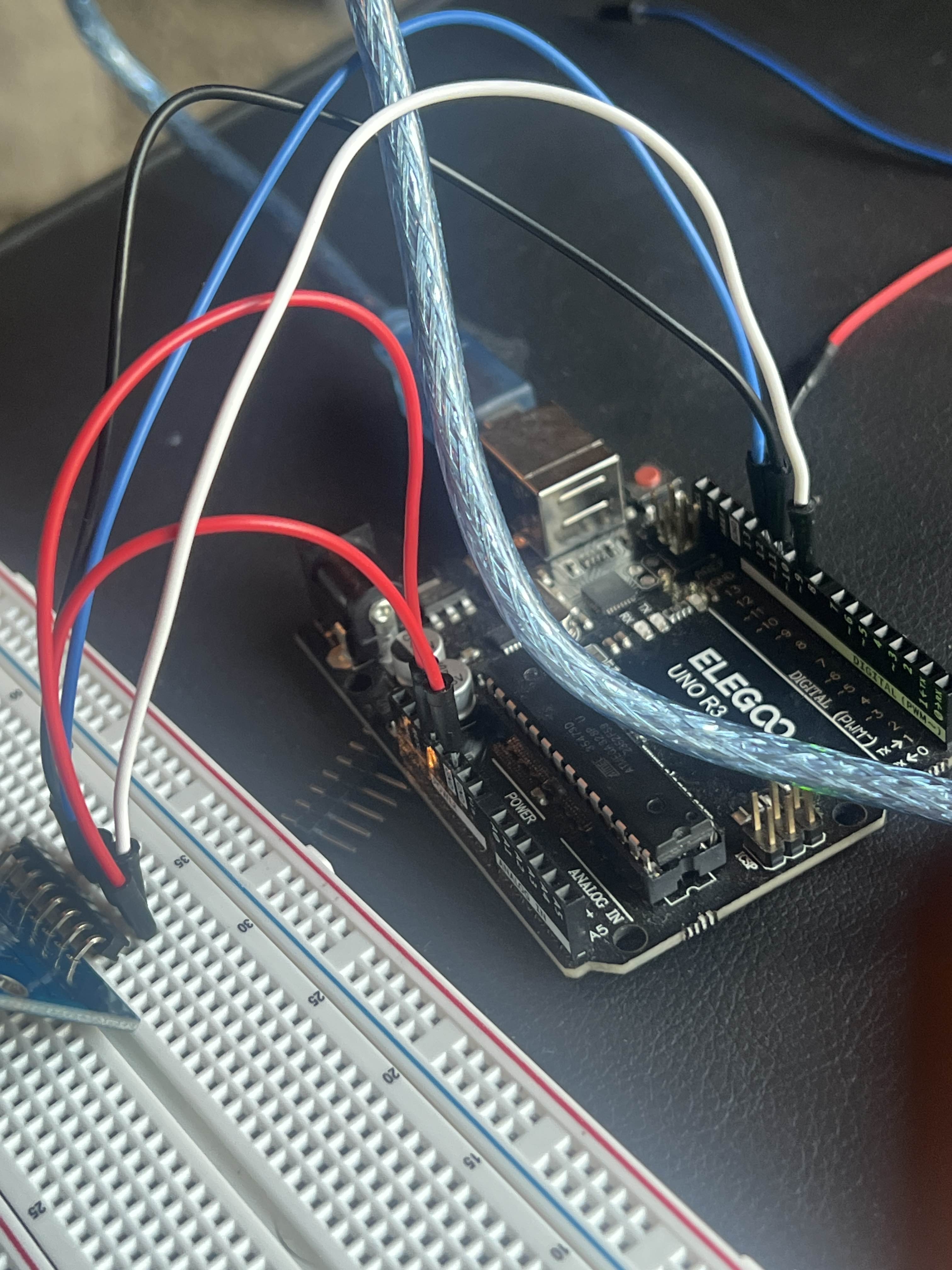
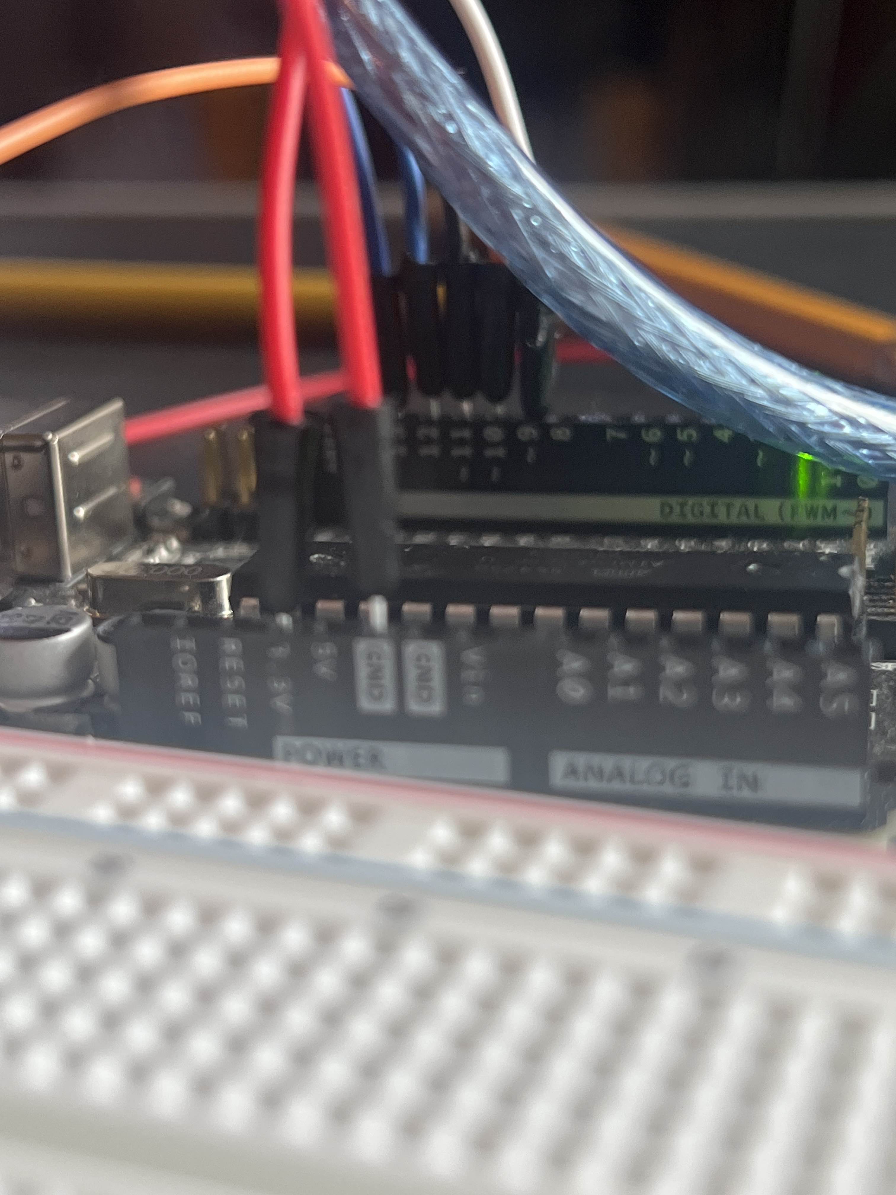
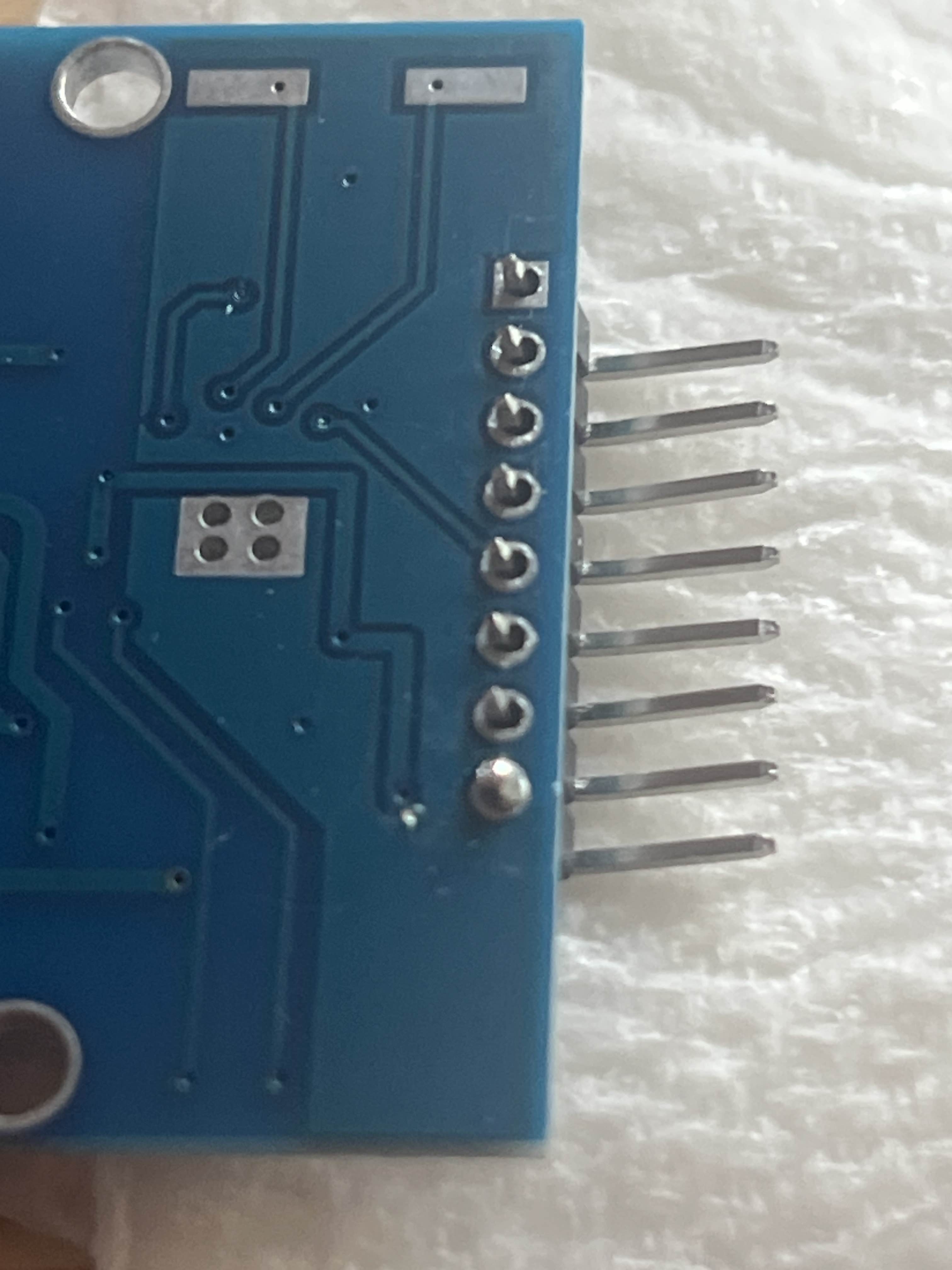
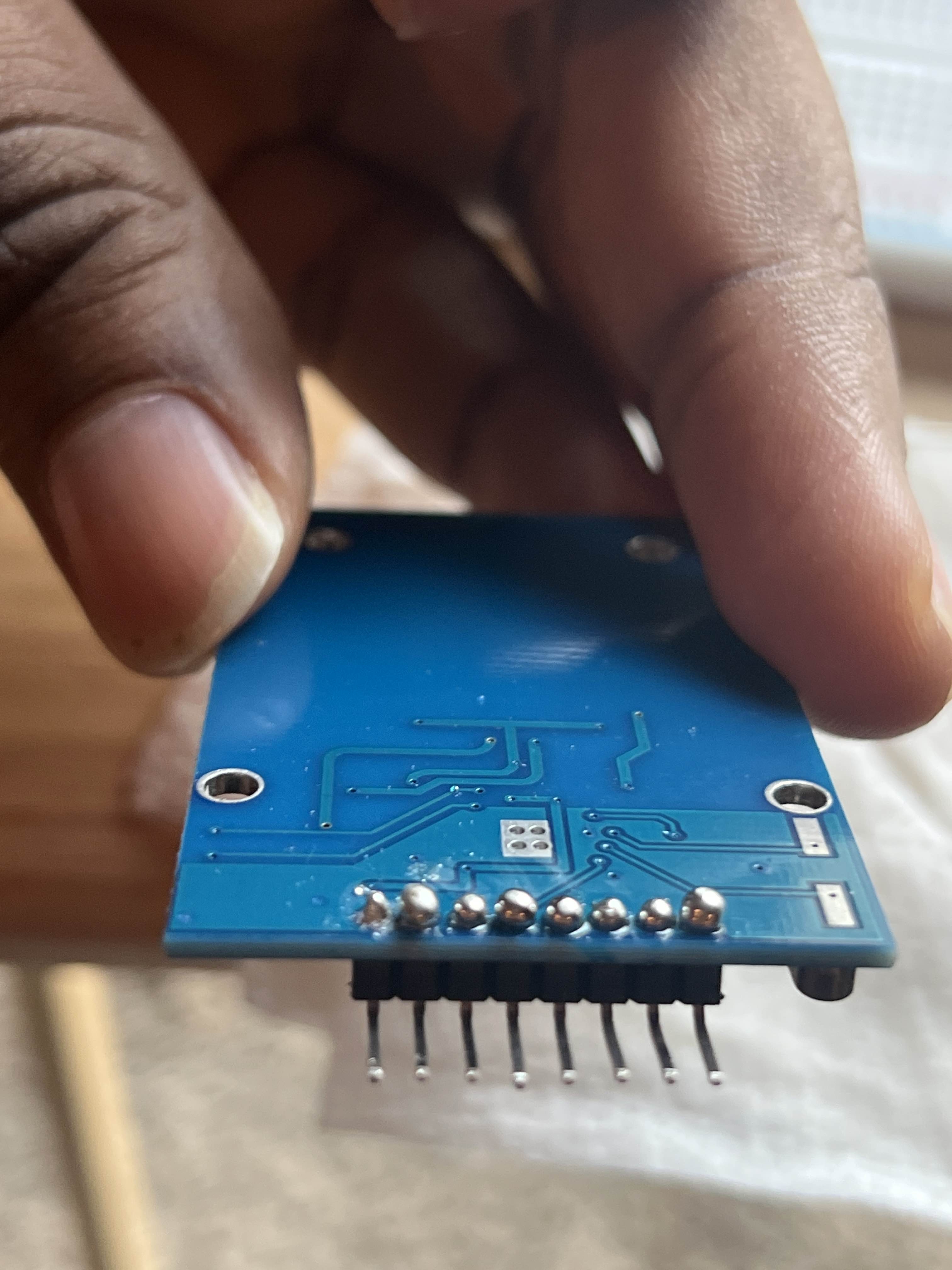
Side:
@Fang can you explain what's exactly happening?
So what i'm trying to do for this project is to let the card scan against RFID making it read out what the card ID is.
Ok, what's the problem
?
The problem is that the scanning is working
or rather it isn't outputing even though it on
So the RFID scans, but you can't see anything on the serial monitor?
I believe so
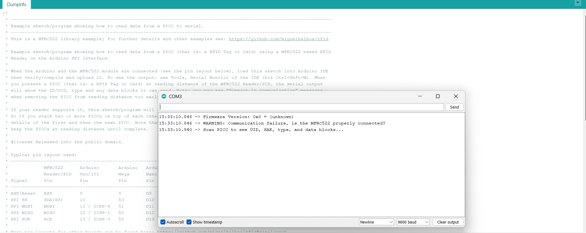
Sorry, I am busy with some other work as well. Try uploading the example DumpInfo
@Fang
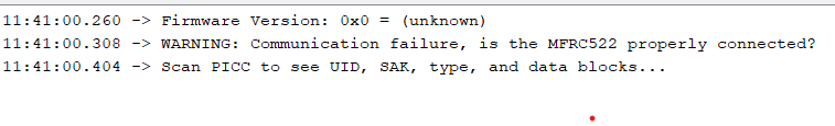
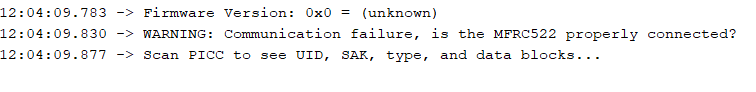
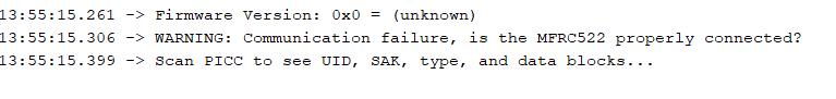
See what Warning says
Do a complete re wireing
oof ok
Step 1;
No, don't do like that, first always plug the Module
Coz, sometimes you can get confused while wiring
?
Yeahh.. now starting connecting the wires one by one
I'm so confused-
Its not connected properly
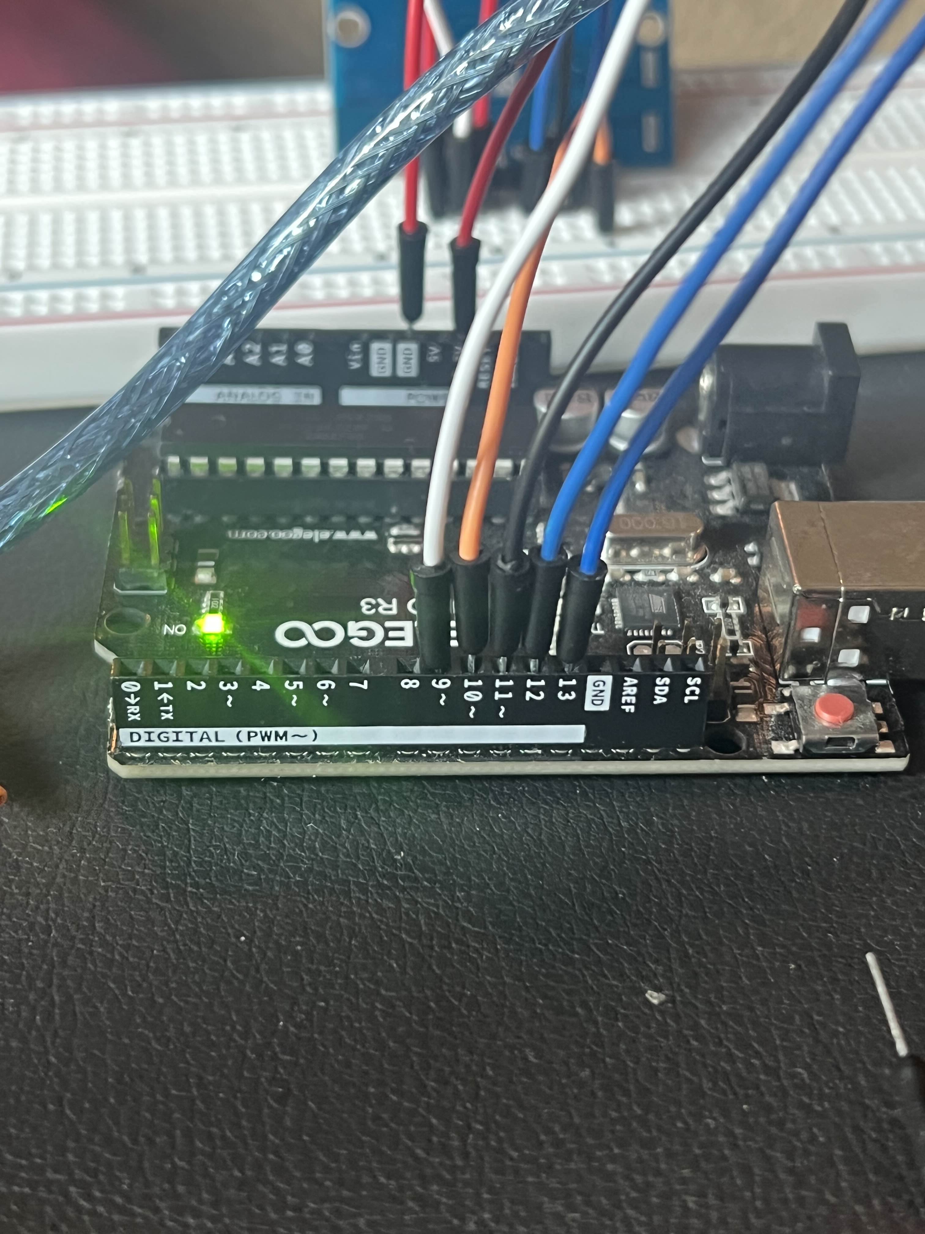
Because, As I checked your connections, MISO is connected to pin 11, instead it should go to pin 12 of arduino uno
Lemme see all the connections of your and put a proper wire diagram for you
Just a min
Switch the white wire from pin 7 to pin 9
the blue wire from pin 11 to pin 12
The other blue
Not the power one
And the red just beside the blue to pin 11
@Fang
@Fang

Connect according to this
Connect as per the diagram I sent
Ok ima reset and follow the diagram
You are literally getting confused.
After your connections, just drop a message. I'll be out for having my dinner.
Brb in a second
Ok I’m back
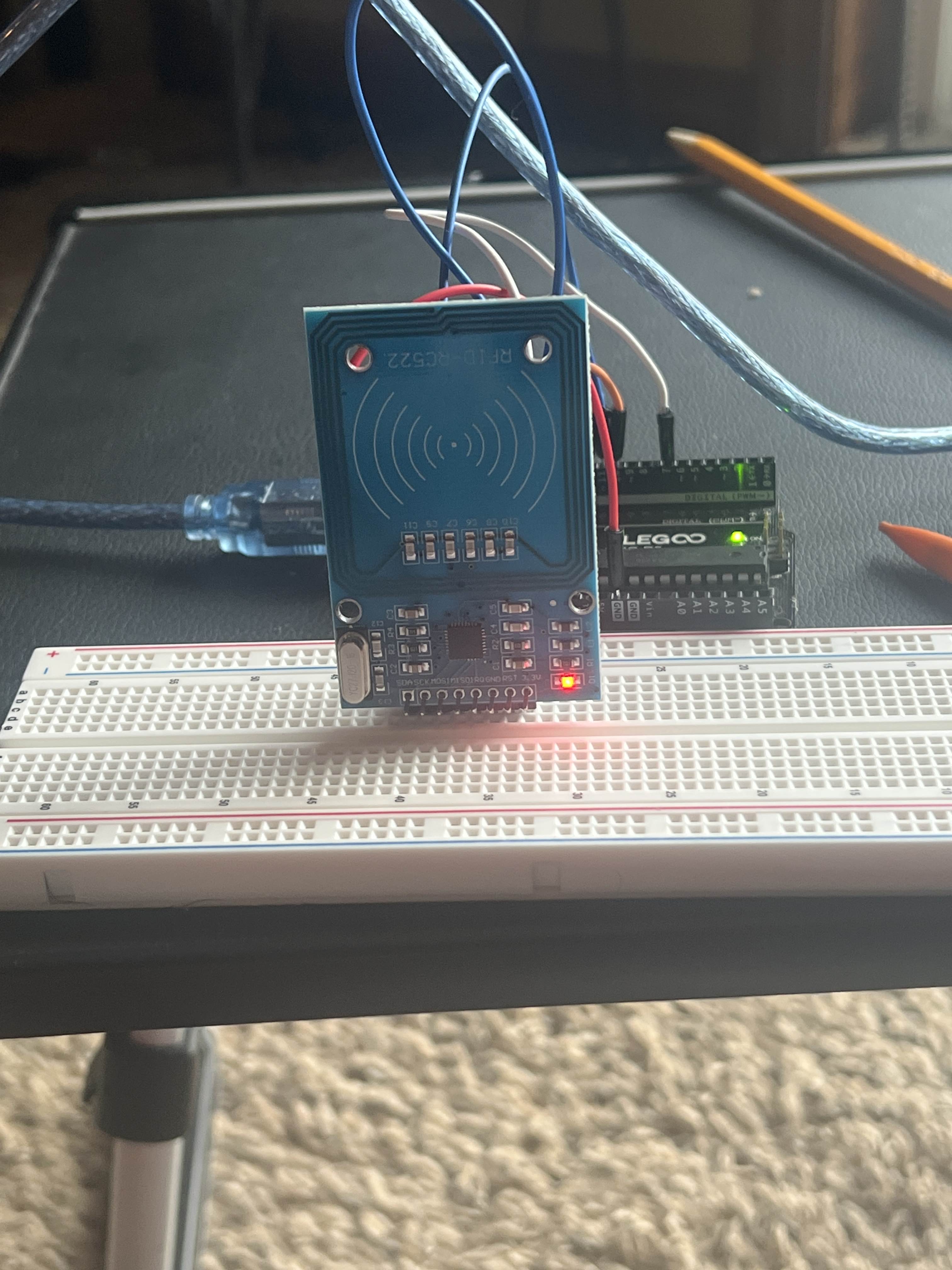
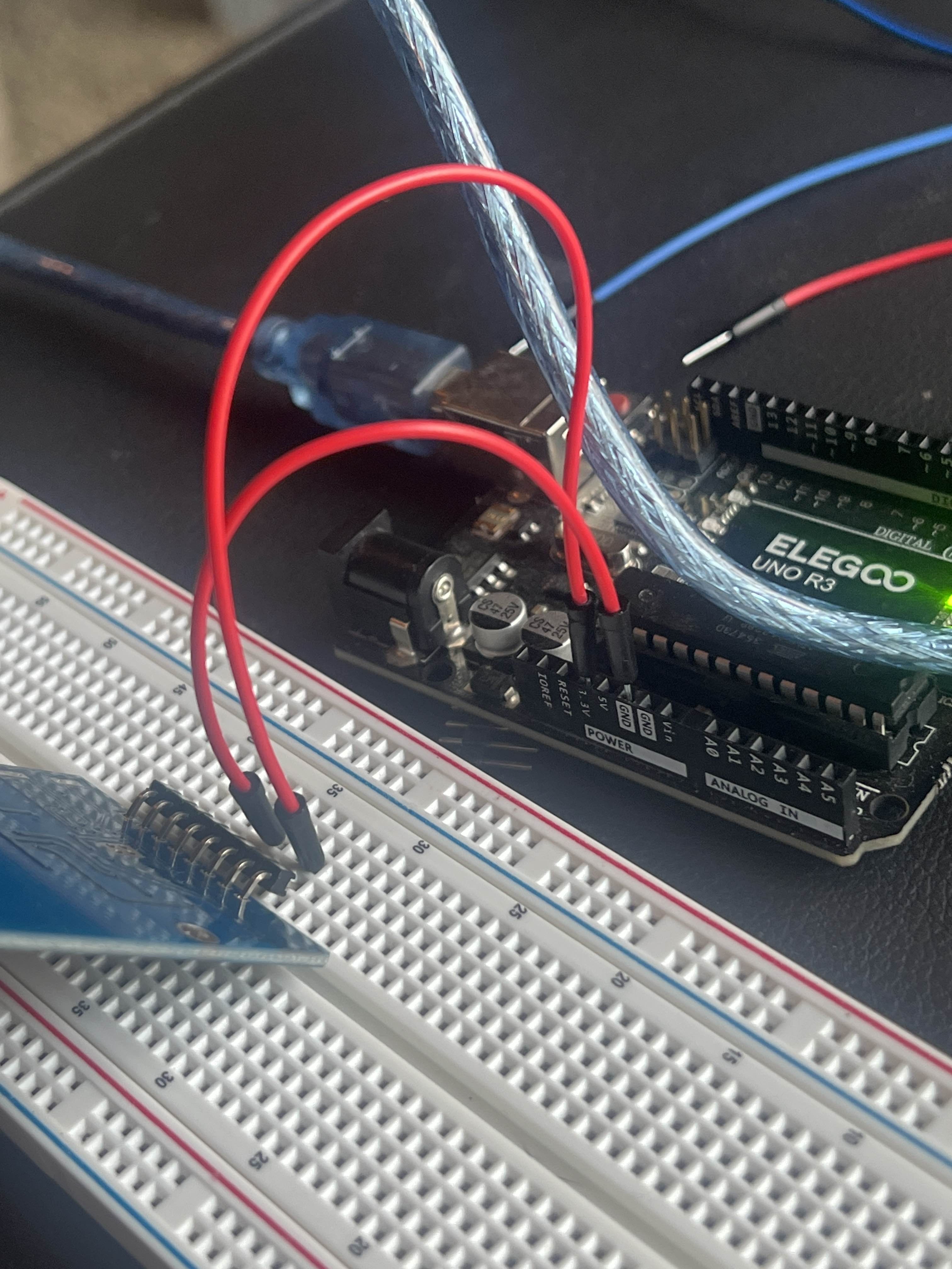
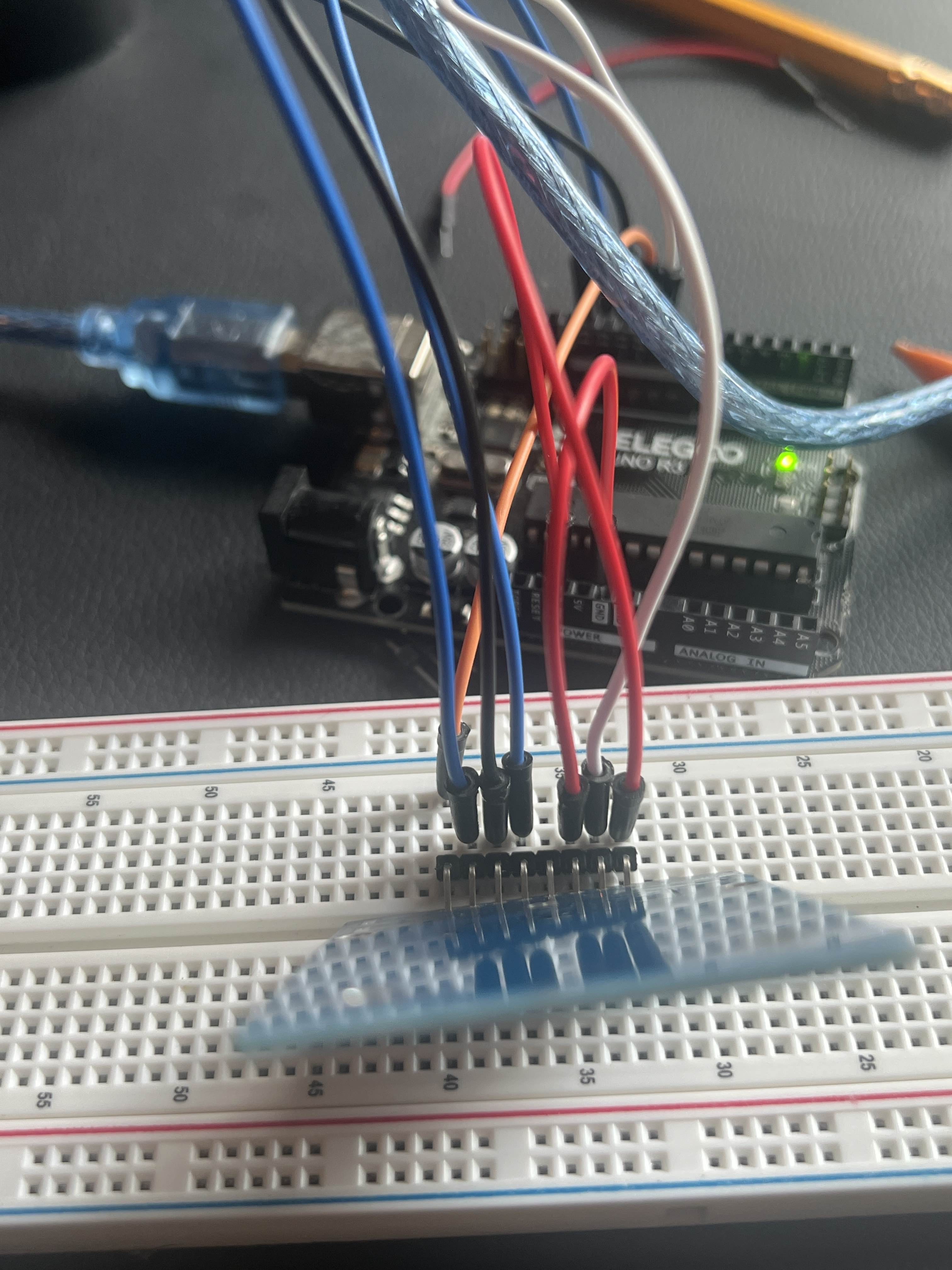
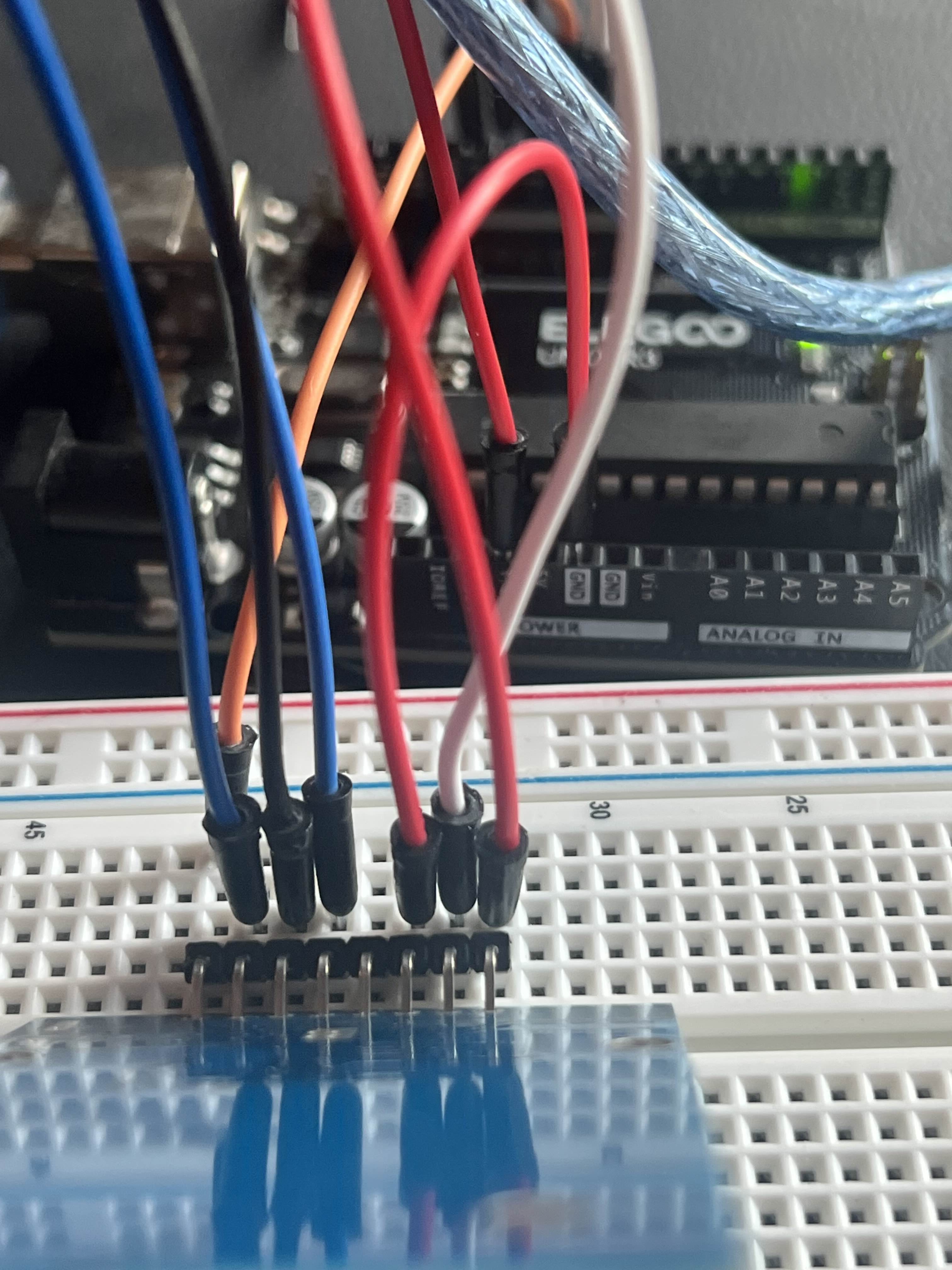
Can you just show the top view?
At the same time as I came
@Fang
^
@Coder_DO_As_Impossible
idk why but I feel like I need a longer wire or something cause it still saying the same thing
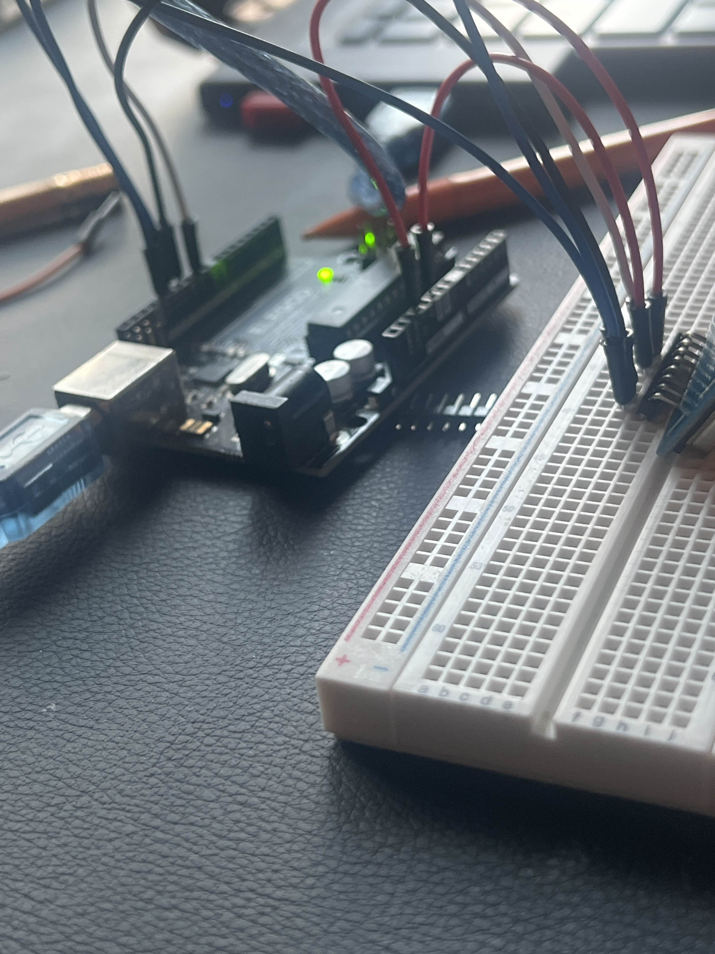
Can I get something like this?
you want me to reset and copy the first image?
if that what your asking? @Coder_DO_As_Impossible
Nope, just the angle of pic
Sent
@Coder_DO_As_Impossible
In that pic both the module and arduino was clear to see
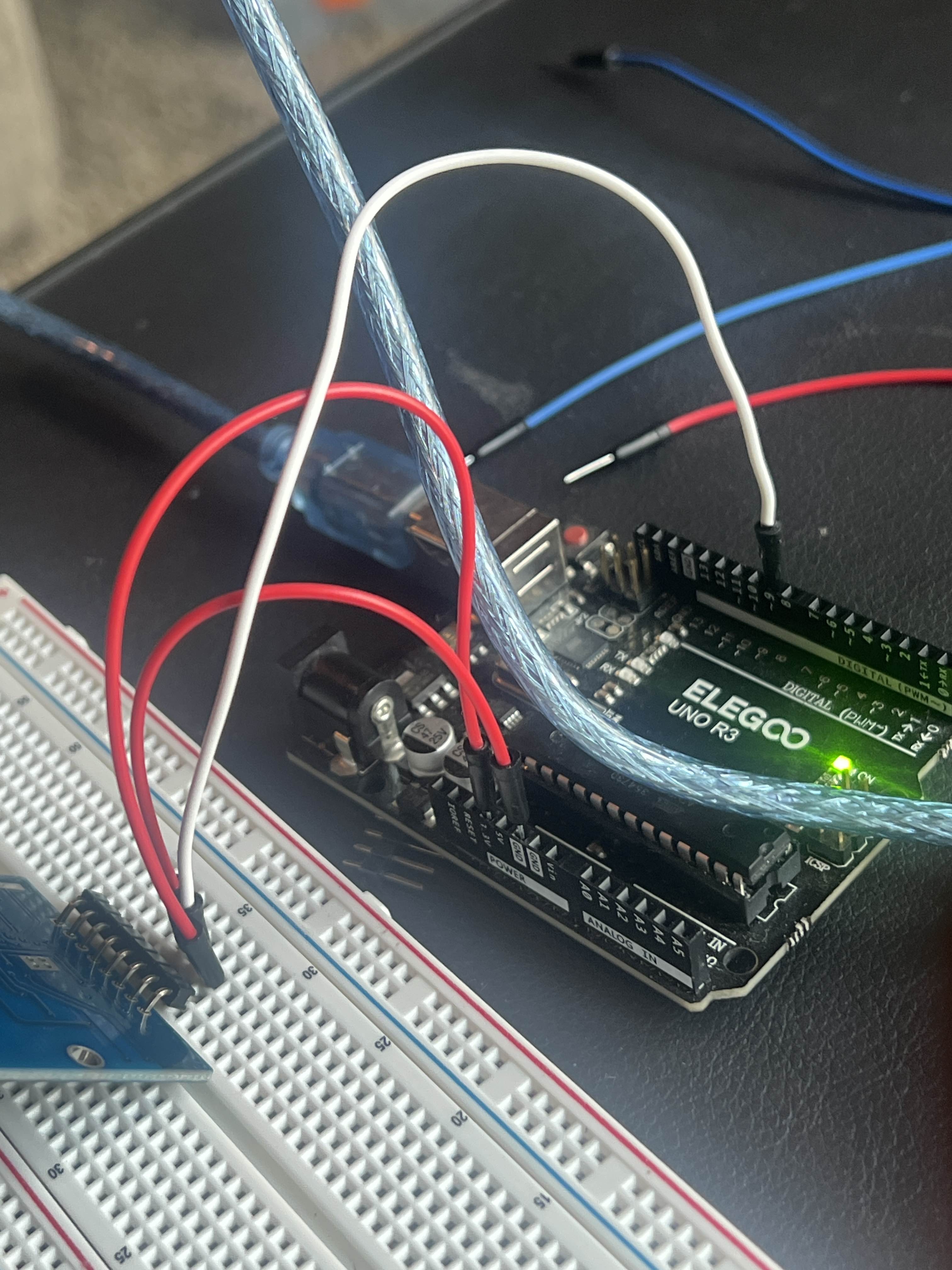
Is this better? @Coder_DO_As_Impossible
Yeahh
You have connected both the blue wires as per the diagram right?
yes i have follow the diagram
OK, now what's the output?
i jsut don't get what im doing wrong
Umm... Lets figure out whats the problem.
Just a out of topic question. What's the local time in your region rn?
it's 1:56 central
AM or PM
pm
Its past midnight for me, but lemme check your problem first, then ill sleep
ok
But if you want we can just do it another time so you won't feel sleepy while trying to help me 😅
Nah, its okay I'll manage.
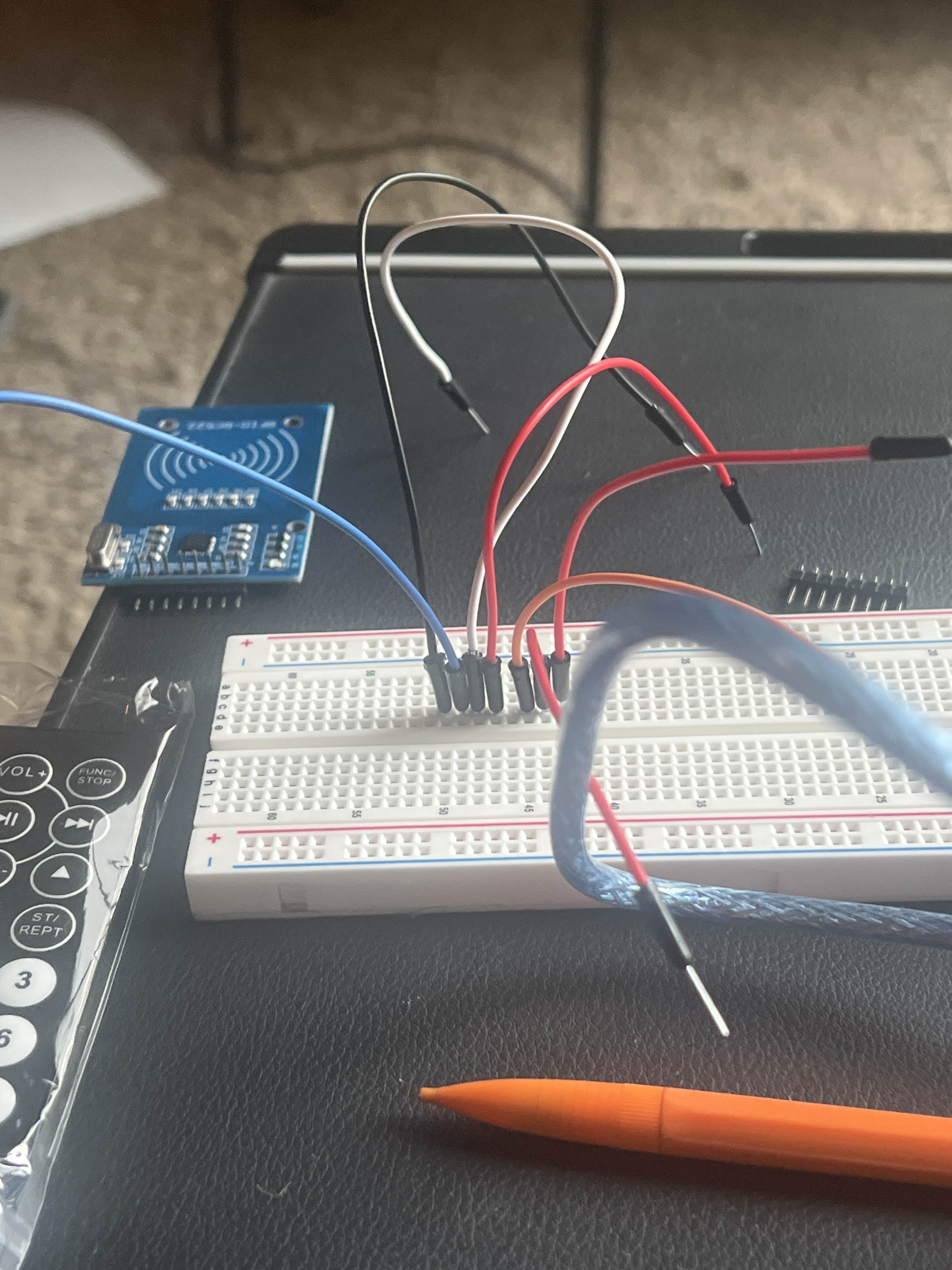
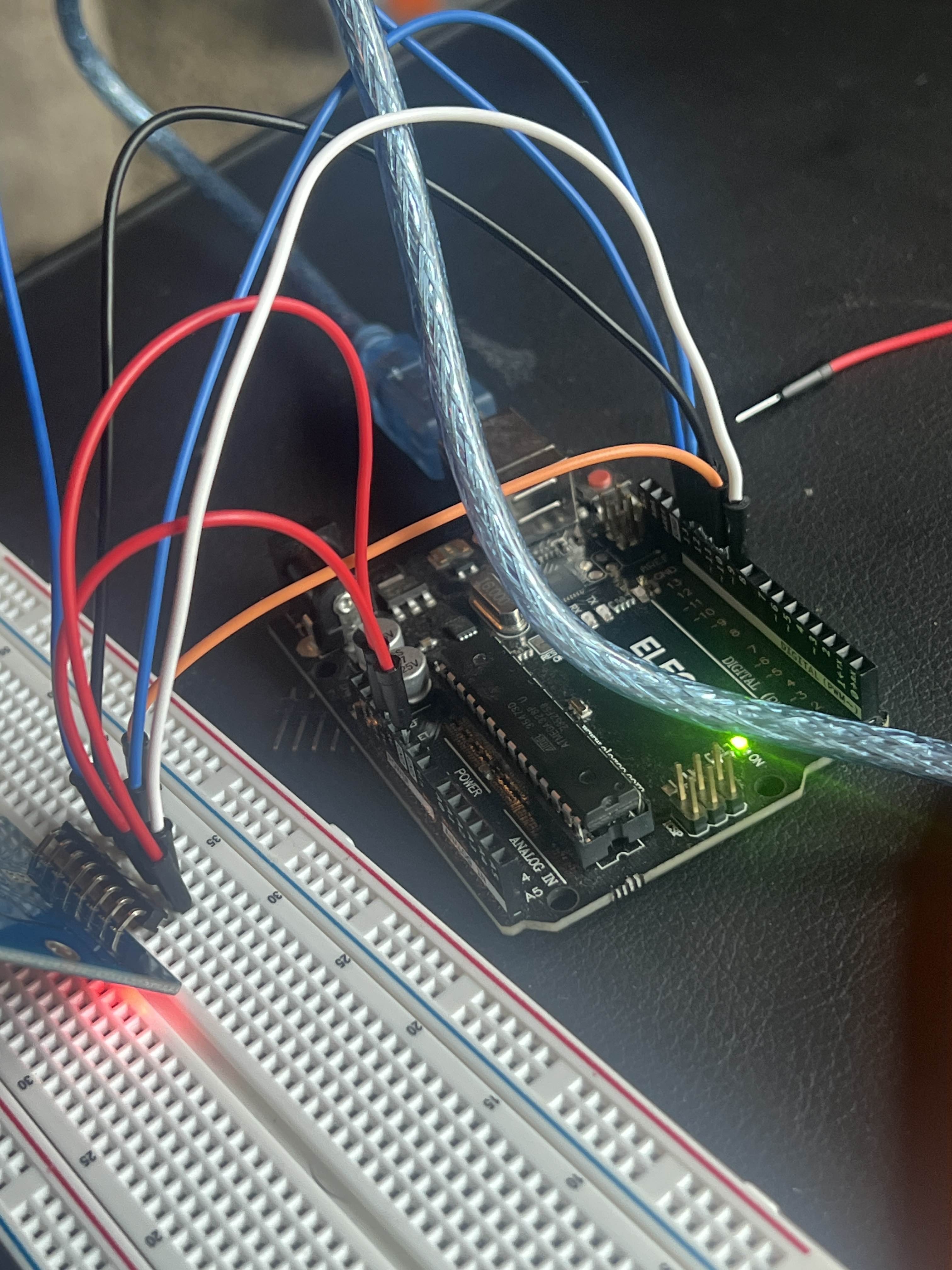
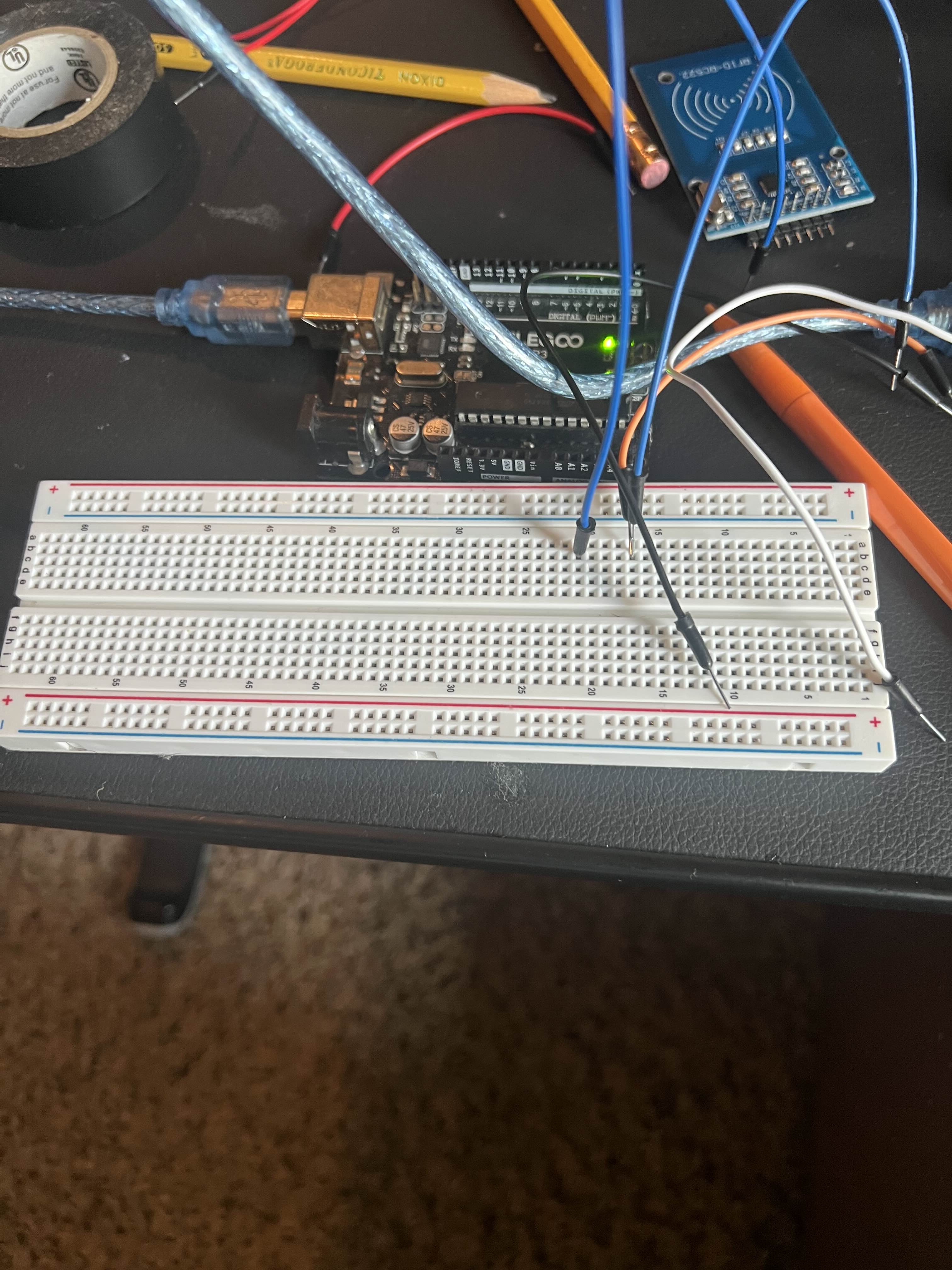
Also here’s what my wire looks like
You shouldn't have removed the module maybe
does the module have to be connected at all times while doing wiring?
if so then I'm confused since it on once I put it back
| RC522 Pin | Arduino UNO Pin |
| --------- | --------------- |
| SDA | D10 |
| SCK | D13 |
| MOSI | D11 |
| MISO | D12 |
| IRQ | Not connected |
| GND | GND |
| RST | D9 |
| 3.3V | 3.3V (not 5V!) |
So this is the connection which you've connected right now.
yes
I've even wrote it down myself as well on apper
ye
try uploading this code
And tell me what's the response
onto new file or the same one that check our wires?
@Coder_DO_As_Impossible
Its your wish, try uploading that code. After that just tell me the serial monitor output
Okio
Give me 1 second
@Coder_DO_As_Impossible
are none of the wires responds to it??
Did you ever connect the module to 5V?
Ever once
and power it?
no?
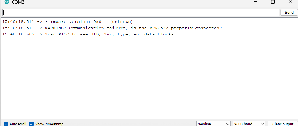
This is indicating that the module isn't responding
no??
I've always connected to 3.3v
because that was the direction
did i do something wrong was I suppose to use 5v??
Ok, either this indicates the problem of any one of the cable or maybe the board broken or something else
You should NEVER use 5V
guess I'll get new cable and board just in case then
I am now in a lot of confusion
Like this is some new error, which I ever came across RC522 .
@Fang Try checking all the wires are proper or not.
Do you have a spare arduino?
i do but they aren't long enough to connect to certain ports
How come arduino should be longer?
idk
i gotten the starter pack
Oh, okay
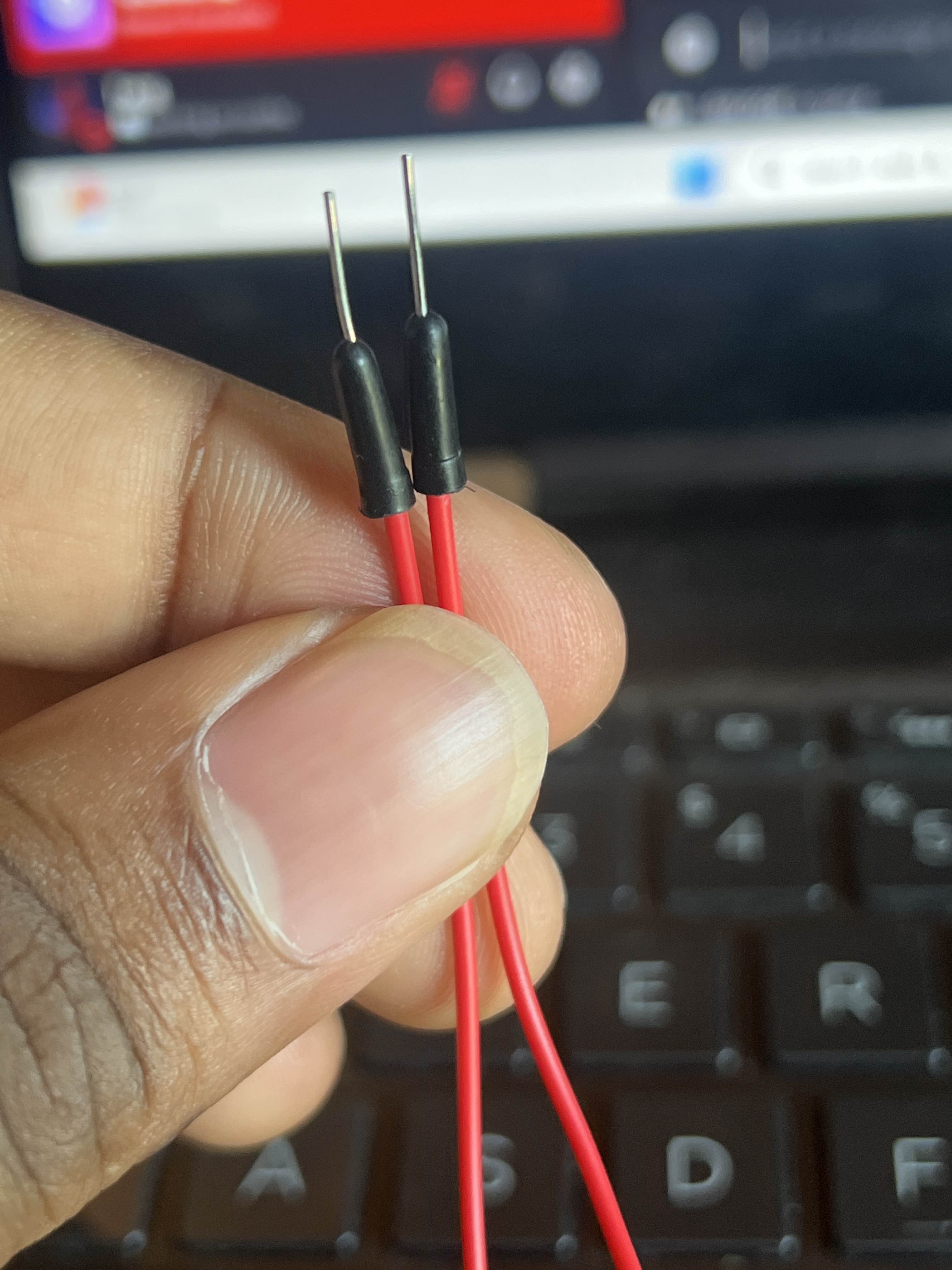
does it count as broken if the metal part is slightly bend?
Which metal part?
You haven't soldered them yet?
no? like i said this is a starter pack-
I literally noticed it now
🤦
@Fang sometimes the connections aren't good enough without soldering. This may cause these errors, like the headers aren't touching the pads properly etc.
so do i need a soldering kit?
You should do a proper soldering
how do i solder something like this though-
😅
With a basic Soldering Iron
Get one
It will be useful in future purposes
To solder it, just plug it in the breadboard as you have done, and solder from the backside, where the header's pin is exposed out of the pad.
I’m so confused because I get bread board that doesn’t need soldering
so i gota solder the pins?
Like those metals?
ABSOLUTELY!
Trying to use a breadboard without soldered headers is like trying to plug a charger into a socket using just loose wires and tape — it might touch, but it won't really work.
- Credits to chatgpt for me giving me the example to explain this properly.
pins sticking through pads will never work
alrighty guess for right now it on hold until i get a soldering kit 😅
I noticed this after making him rewire this much times 🤦♂️
also one more question is it better to have rfid laying down or standing up straight?
Its your wish. How you feel comfortable, you can solder it that way
But you NEED to solder it.
Well, I am gonna sleep now.
okio I'll order it and learn how to solder after that I'll let you know
it's easy to miss in pics, but it happens all the time 😉
Idk if this is right but is it right?
@AnonEngineering @SNV008!
First time soldering btw
Nice 🙂 take everything slowly. Soldering first time? https://youtu.be/Qps9woUGkvI
oneTesla
YouTube
Soldering Tutorial for Beginners: Five Easy Steps
If you've ever wondered how to solder electronic components, you've come to the right place! This video breaks down soldering technique into five steps. I'll show you how to solder through-hole components as well as how to solder wire.
Brought to you by oneTesla! Check out or DIY Singing Tesla Coil Kits at http://onetesla.com
The oneTeslaTS ...
If you cover up the header pin and the pad completely then it should be good to go
Also ngl I burnt myself and almost set the house on fire when I dropped it-
Is this good to? @SNV008!
First pin is good, second pin, its a like fat boy 😉
Do I need to keep soldiering the second one?
No, just leave it as it is. You'll proper soldering over time. Just continue with the further.
If you wanna dedicate, then just remove some solder by adding flux to it, and contacting the iron with it.
Alrighty again thank you will let you know how I’m doing once I’m done
Here the update @SNV008!
Well it's rough and patch work, but you are good for a beginner. Make sure there are no short between the pins.
Well, my time to wake up for the most is done. I need to rest for sometime rn.
short?
@SNV008!
Yes due to those excessive soldering present minute shorts can happen. Just so to prevent, run a blade between every gap.
As you get better the finished connection should look like a cone, not a ball
@AnonEngineering Thank you for coming. I can sleep now peacefully.
oh wait does that mean i gotta start over?
On mobile, hard for me to help much 😁
because there all a ball-
Oh same here, and it's morning 1.50 too here
Its okay for now. Just do as what I said. Run a blade. As better into the practice, you'll start getting the perfect cone
Fang, just make sure no 2 pins touch, that is what "short" means
oh sorry i was just making sure
also i ran a blade between and seems to be good
Good night for now.
@AnonEngineering Idk how much you can help, but I will sleep now.
@Fang you are good to go. Do the connections now, but in someone's supervision. I hope anon will be.
alrighty wish me luck
That's a good tutorial, follow it exactly
Have a good night
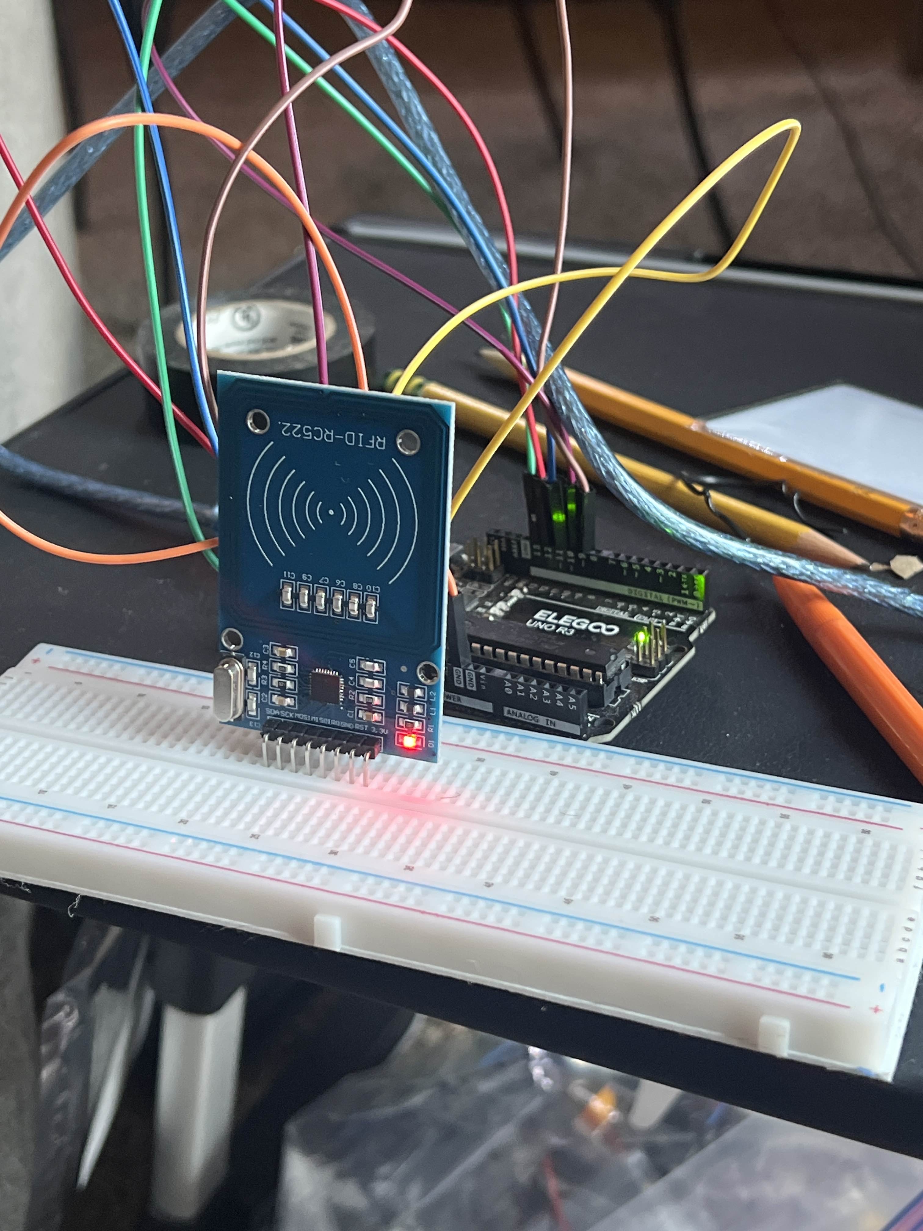
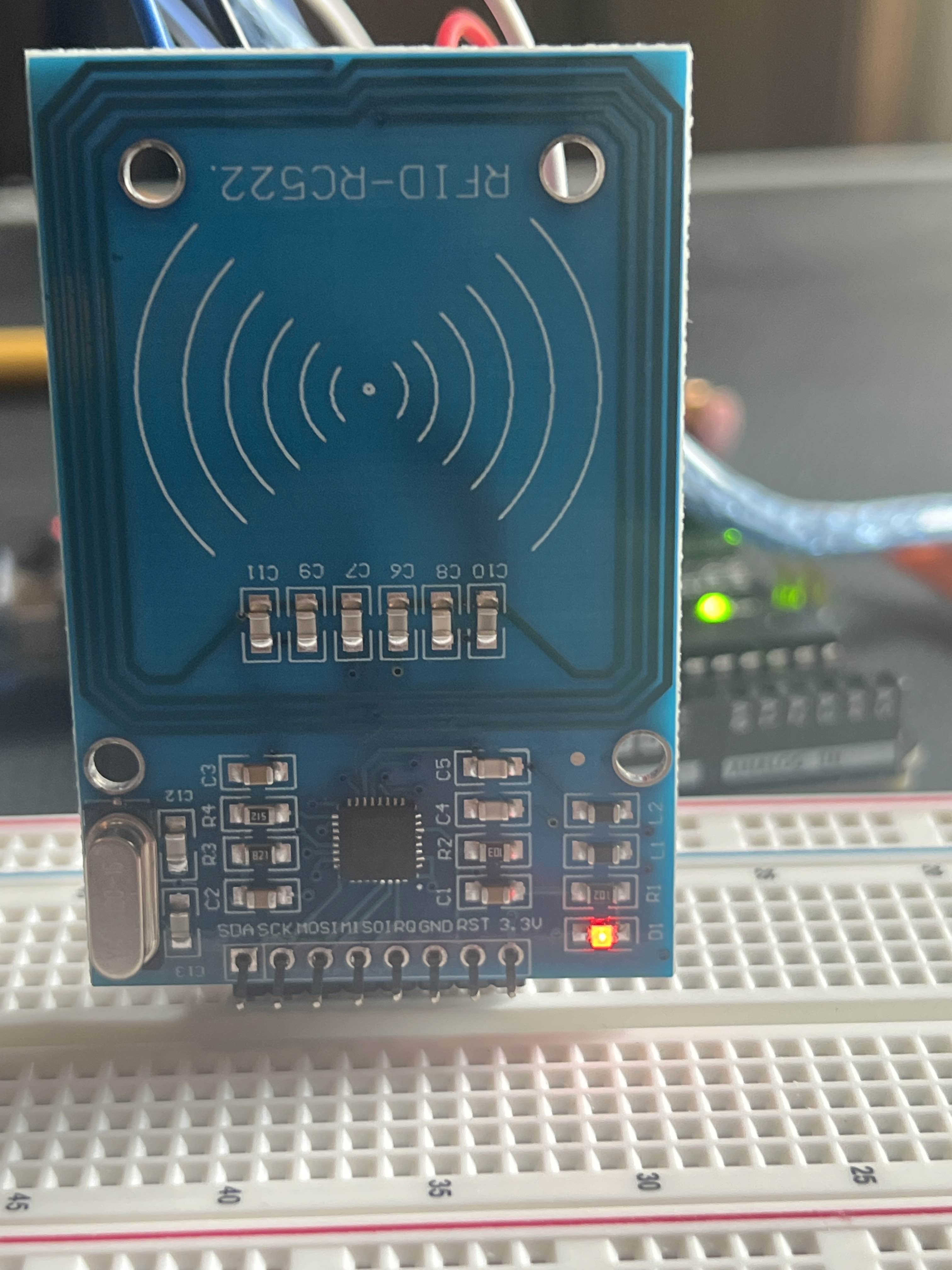
Lights up, always a good sign
bro wat-
Means it's getting power at least
ik but im talking about the error ;-;
Double check pin connections
You may need to seat the board down more
Walk it side to side until it sits flush to bread board
Still isn't talking, you may need to resolder some pins
It should seat better, try a different row
Basically if any pin has a poor connection you'll get that error
The code basically asks the module "who are you?" And gives that error if it doesn't get an answer
Understandable
Dunno why it won't seat flush, the black connector should touch the bread board
Up like that one or more pins may not be connected
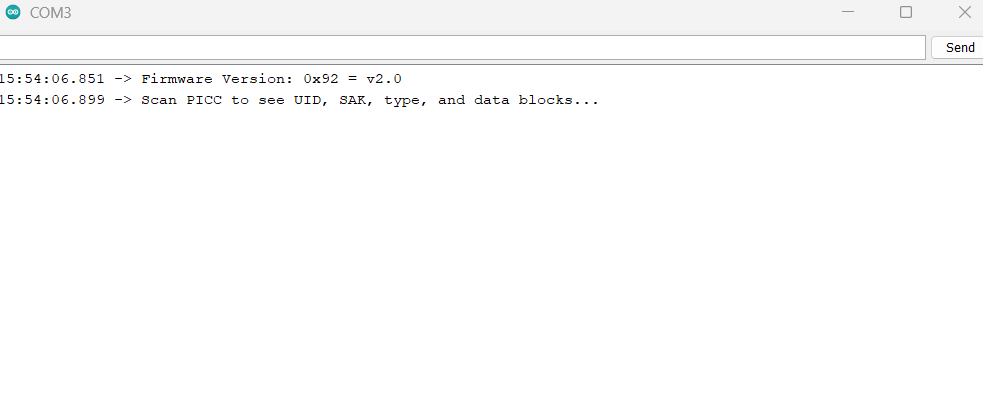
That last message was better
so is it finally working
🎉
wait give me 1 sec
Should give you data with a MIFARE card / tag
👍
Again thank you so much!!