Digispark ATtiny85 Inputs doesn't want to work
Hello,
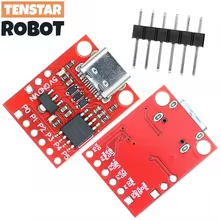
i am getting crazy with my ATtiny85 with Micronucleus Bootloader (digispark clone).
I want to read one analog input. Here is my actual sketch:
####
const int PowerLEDin = 2; // Input PowerLED vom BT-Receiver
const int SYSCTRL_Out = 1; // Output SYSCTRL zum BT-Receiver
bool PwrUpOK = false;
void setup() { pinMode(SYSCTRL_Out, OUTPUT); digitalWrite(SYSCTRL_Out, HIGH); delay(250); digitalWrite(SYSCTRL_Out, LOW); delay(250); digitalWrite(SYSCTRL_Out, HIGH); delay(250); digitalWrite(SYSCTRL_Out, LOW); delay(1000); } void loop() { int LEDstate = analogRead(PowerLEDin); if (LEDstate >= 500) { digitalWrite(SYSCTRL_Out, HIGH); } else { digitalWrite(SYSCTRL_Out, LOW); } } ##### The blinking in the setup was a test, if the setup is correctly working. I already tried "0" for P0 and "2" for P2 as input. My only chance is the builtin LED to see something. Nothing happens when I connect the Inputs to GND oder +5V. I also tried as digital input with and without Pullup (INPUT_PULLUP) - nothing happens. I tried an old digistump with digiKeyboard but my computer doesn't recognize it as an usb input - only a windows error occurs, that the usb device doesn't work properly. Where is my fault or thought error that the inputs doesn't work?
void setup() { pinMode(SYSCTRL_Out, OUTPUT); digitalWrite(SYSCTRL_Out, HIGH); delay(250); digitalWrite(SYSCTRL_Out, LOW); delay(250); digitalWrite(SYSCTRL_Out, HIGH); delay(250); digitalWrite(SYSCTRL_Out, LOW); delay(1000); } void loop() { int LEDstate = analogRead(PowerLEDin); if (LEDstate >= 500) { digitalWrite(SYSCTRL_Out, HIGH); } else { digitalWrite(SYSCTRL_Out, LOW); } } ##### The blinking in the setup was a test, if the setup is correctly working. I already tried "0" for P0 and "2" for P2 as input. My only chance is the builtin LED to see something. Nothing happens when I connect the Inputs to GND oder +5V. I also tried as digital input with and without Pullup (INPUT_PULLUP) - nothing happens. I tried an old digistump with digiKeyboard but my computer doesn't recognize it as an usb input - only a windows error occurs, that the usb device doesn't work properly. Where is my fault or thought error that the inputs doesn't work?
7 Replies
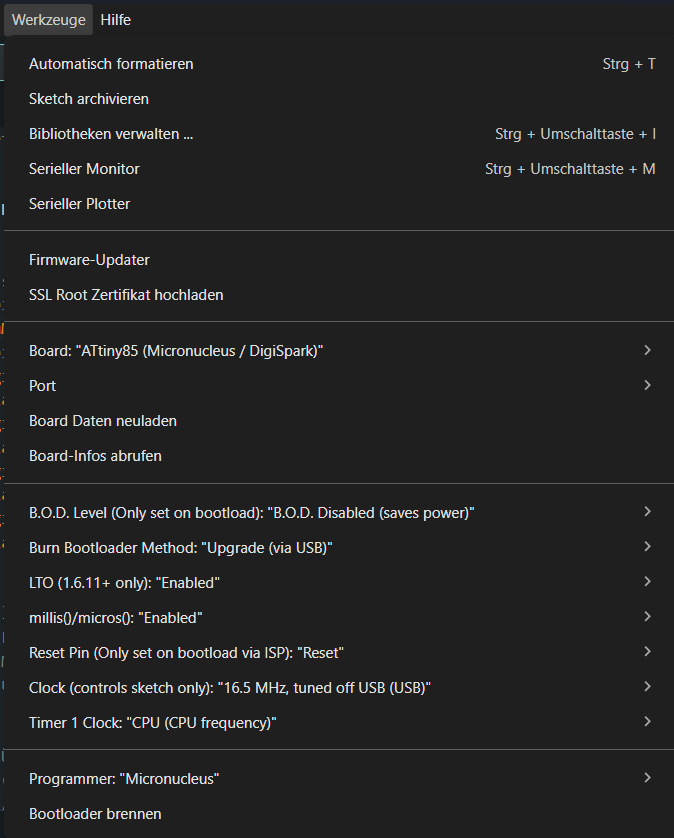
Can you provide a screenshot of your Arduino IDE -> Tools menu?
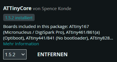
What exact core are you using? There's a slightly modernized version of the old digistump core
Well okay there was a slightly modernized version at https://github.com/ArminJo/DigistumpArduino/ as that was an improvement over https://github.com/digistump/DigistumpArduino but now they just say to use https://github.com/SpenceKonde/ATTinyCore.
So it's really important that we know what core and what version you use for that board.
Thank you for your response.
The board:
Device has firmware version 2.5 Device signature: 0x1e930bI use ATTinyCore 1.5.2 from Spence.
Mhm. The pin numbering for analog pins is weird.
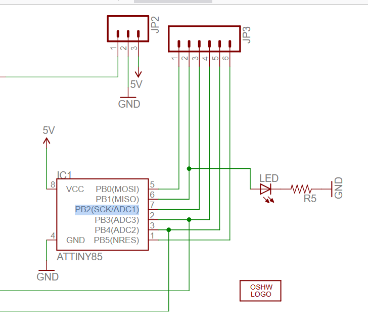
Reading the core code and the datasheets and schematics, you seem to want to read the analog voltage off of what's labeled "PB2" on the board, right?
Which is in turn ADC channel 1
In my reading of the
analogRead() function, you must supply "1" as in "ADC1" as the argument to the function, not "2"
because the "pin" is directly used as the ADC channel number
In fact, to be 100% compliant, you should be doing an
The macro
Further suggests that analog input "1" is digital pin 2, which is also PB2.Thank you sooo much! With A1 it works!! Now i know, where i have to look. Thank you again!
Great!
The pin mapping and relevant code is in
* https://github.com/SpenceKonde/ATTinyCore/blob/1.5.2/avr/variants/tinyX5/pins_arduino.h
* https://github.com/SpenceKonde/ATTinyCore/blob/1.5.2/avr/cores/tiny/wiring_analog.c#L64-L89
You can mark the topic as "solved" too: https://discord.com/channels/420594746990526466/1145716419464527953