Apparently my code's useless. Let's improve it.
As per your request, https://discord.com/channels/420594746990526466/451155251580633089/1391377704473071627 @nis
141 Replies
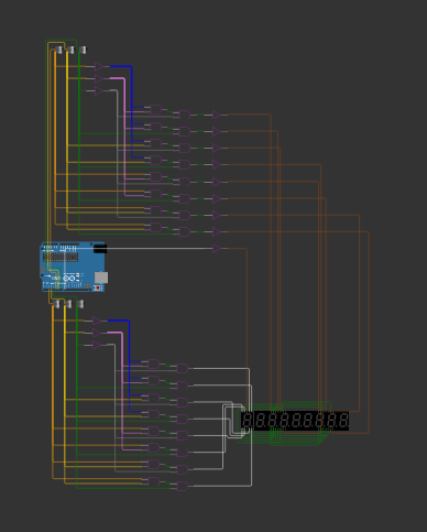
thats my code
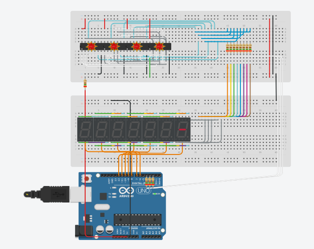
tbh all i want it to do is literally power pin 3 up and make all the common cathodes of all digits except 1 so they dont light up
powering pin 3 goes through my binary decoder and translates it to wire 8
which is supposed to power the
. in the last digit.
when i directly short pin 3 to VCC of arduino the . lights up without issue
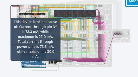
but when i use "1" and power it with code the chips go broken
oh that yeah it probably just kept re-writing the same thing and lagged it out.
so i am asking, why do the chips get broken only when powered with code. direct circuit short works fine.
remixing :P
possibly. its misbehaving. so i either have to switch to real hardware or just use another sim?
why do you think i do not know what i am doing? i am pretty new to multiplexing, if i am being honest. but im pretty sure i know what i'll do, considering i have built clocks before. what i am doing this time is just adding ms digits to it and multiplexing in an effort to manage to use an arduino UNO when i build it physically, even with more pins to manage from the segment displays.
well, maybe. but this thing is just something really unoptimized i am using to test out my wiring.
though, you really helped. thank you for it.Sorry, I was out for a work. What's the update?
@myzstral https://discord.com/channels/420594746990526466/451155251580633089/1391361219276967936
I got your response, but I don't understand the usage of 3 AND Gate ICs
its used for my multiplexer
iirc i gave u a link to the multiplexer i took insipration from
https://discord.com/channels/420594746990526466/451155251580633089/1391362186101653548
Do we have a link to diagram or emulation?
^^^ check that link and you'll see what the AND gates are for
i forgot to add it, sorry
adding it rn
i cant pin it :/
Ok, I got it, but I don't understand then the usage of HEX decoder.
its used as NOT gates
Have you tested one digit by itself ? Without multiplex
Hmm...
wdym one digit itself
it does work
like
as i said
even with multiplex
direct short circuit through a resistor to arduino's 5v works
but when i send the signal from the arduino through code, even with the resistors, the chips break
its probably the sim just misbihaving
In real life ?
nope ok
That is on VERY hard cirduit to trace....
either because of my horrible wiring or the multiplexer that has a few million wires connected to it yes
i mean it does work even though it shows the chips "broken"
i mean i tried making it as easy as possible by using as much colours for wires as possible
@myzstral Redo the wiring work, neatly and send the updates here. If I am not, then Darwin will surely help
it probably has no wiring issues other than some wires going on top of eachother and hiding the ones underneath
i tried to make it as clean as possible. i dont even know how to make it cleaner anymore
tho i will try
Send each and every update so that you are supervised and all of us will get to know the output.
okay
Both are almost similar
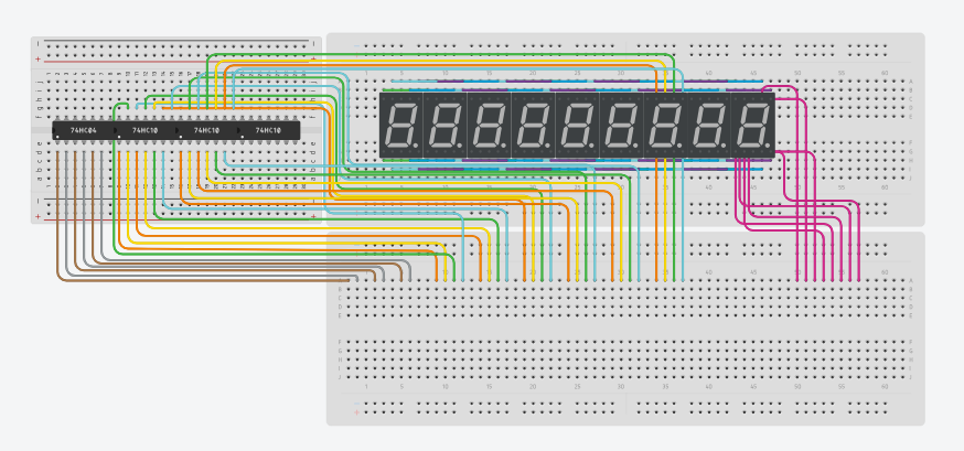
this is what i mean by overlaid wires
at first you're like... "yep thats defo a single gray wire"
then you pull it up and go "it was 2... wires?"
then you pull it up once more and go "3 WIRES!?"
Well, I wont be available for 2hrs straight from now, if I can then I'll keep checking. Either Darwin or nis will help.
So Good Luck with it.
not sure if i'll be on for 2 hours
ben here for a few hours already eh
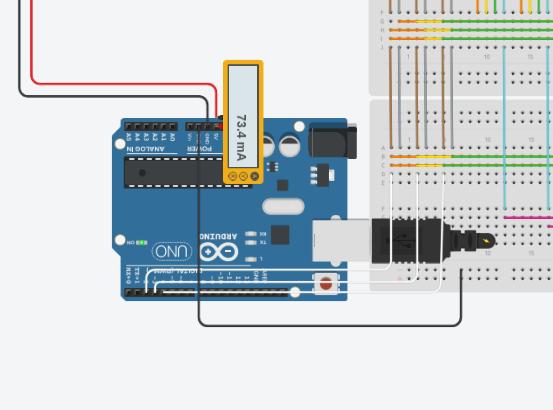
@myzstral why - really why - do you have a resistor on the 5v rail from the ardiono
basically it was burning the ICs at one point
take it off...
and tinkercad was showing "ICs need 833mV"
then i calculated a resistance to drop 5v to 833mV
and it stopped for a while
sure
that resistor was the culprit
wow
amazing. a single resistor making me suffer for hours.
thanks darwin
When you are running and it show the blown up thing - hover over it
It tells you what is causing it
i did hover it
yes at one point
it said
the ICs were overloaded
And it said 5v is over the 2.33 VCC
( prolly an input ) but i messed it up and changed the input to the chip
it did fix it not for long tho
it says diff stuff at diff times lol
You are also overloading the arduino pins
I read the message.
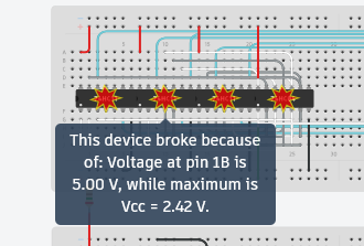
Which is where one ponders - why is VCC 2.42 V
The next step is the inclusion of resistors on the common pins of the display
The rest of the rats nest - I am unsure of
Well the code aint much
uh i updated my circuit a bit
did this
and also
i updated the code a bit
to send all 8 binary values
to see if the segments work properly
in all digits
this is the code
i'll do that
it didnt light the segments up
It is just the pin mode - it wold not affect any other code
IS this an exercise ? like test or something - I am unsure why you are not just using a controller chip
sorry my internet crashed while i was explaining
so i put leds to test my binary output code
it did work
but the segments arent lighting up
well i like understanding how things work
and doing them myself
:P
How are you turning each digit on ?
<wanders off in a daze>
yummm, coffee...
I have the commons seperated. So i power the common of the digit i want on. I iterate through the commons fast so you dont notice it. ( this is js what i plan, havent programmed it yet )
Which is a good plan, but in a real circuit you need to remember that if all the segments are on the common pin needs to sink or source ~80mA, more than a pin can handle. Usually you use a transistor on each digits common pin.
A sink is like an electrically powered switch rgt? Like i send a small current to it and it allows a larger current connected to it pass thru, right? I thought it was called a relay for some reason
yes, the transistor acts like a switch (a relay is also a switch but it's too slow for this application)
you'd "sink" current for a common cathode display, you'd "source" current for a common anode display
(in my simulation like the transistors aren't there, Wokwi doesn't simulate current)
anode or cathode ?
glad I didn't wait for a response, drove 750km since that answer 🙂
The wiring is lacklustre, needs work. Given its a virtual environment use more bread boards to spread it out.
:P
sure
i am rebuilding my circuit in wokwi
issue is
it has gates
and not actual hardware
so i cannot ditermine what components to get when i am done lol
uh so
back to tinkercad? idk
i might build on both
the decoder uses which chips, i can't read the diagram above
AND gates and inverters?
yeah
and gates and not gates
wokwi has both of them (as gates)
yes thats the problem lol
i said it has gates
and not chips
its not exactly a problem
why? inside <whatever chip> are gates
forget it
it will be a wiring nightmare 😉
does Tinker have the chips you are using?
yes
Tinker does have 74HC21 which would make it a little easier to wire...
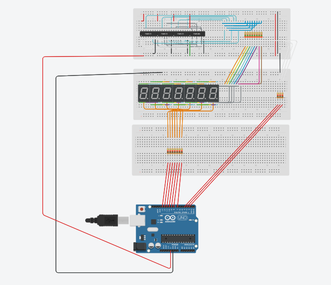
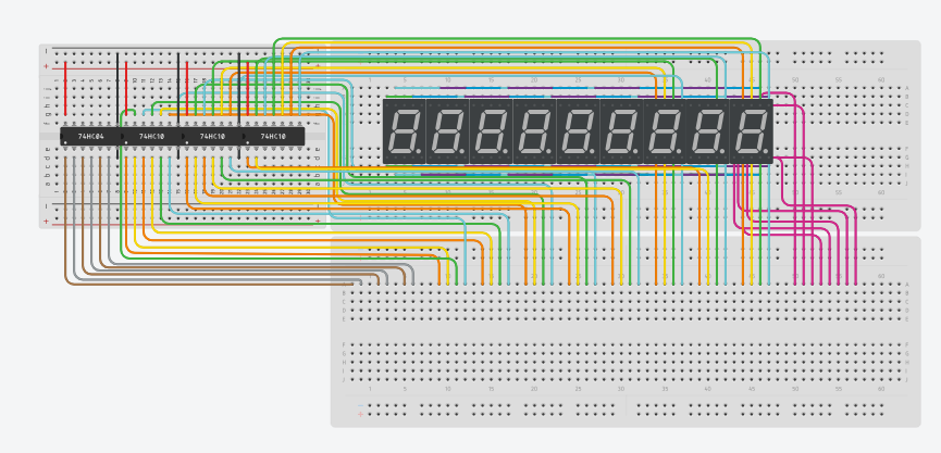
i am rewiring everything
to make it clear, hopefully
i am using diff breadboards for diff stuff
and sort the inputs and outputs to one place this time
why 9 digits? maybe start with 4 just to prove the point
or 1 digit, get the 3 of 8 decoder working first
i'll only be testing out with one digit till i get it right
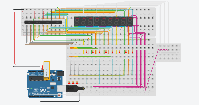
progress update
the chip wiring might still be messy
but meh the wires connected to the breadboard arent messy atleast
with that many gates it'll never be super neat, but try your best to not overlap wires
that does look better
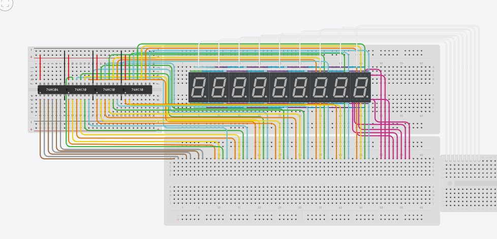
quick question: was color coding those wires a good idea, or a bad one?
may actually be better to not use a breadboard
IRL you'd have the advantage of a multilayer PCB
color coding is a good idea, i always use red for power, black for ground, then pick colors that make sense to you for inputs / outputs
yeah lol
same
good luck on your quest, since the '70's i just cheat and use a CD4511 🙂
as i mentioned, i like learning how things work and implementing it on my own :P
though im not sure if this thread should be in coding help lol
yes, a worthy task
eh, maybe hardware would have been better but just leave it here now
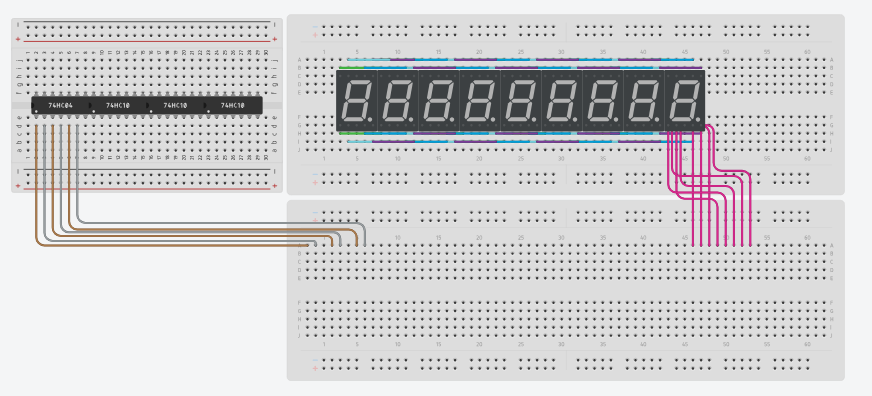
done with the gate wiring
i am planning on switching to hardware really soon, actually.
last time i built a clock i built v1 on hardware
then made it in tinkercad to make "improvements" and "add features"
which never happened
enough staring today. my eyes are already dead enough
rest tomorrow, or later.
thank you for your help, anon
farewell.
wired the commons as well, before i forgot
bye now
I really respect your dedication. You took your own time to make a circuit to help someone.
🫡
and I haven't played with discrete gates in forever 😉
respect*100
Very much appriacted. My greatest gratitude to you, anon
you're welcome, it was a fun exercise 😉
(still a wiring nightmare 🙂 )
Lol
👍
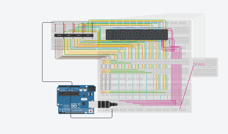
i just had to do it 🙂 , this is very ugly but it works
https://www.tinkercad.com/things/5CSH4tGoAZV-3of8decoderdemo
Now to extrapolate that out to 8 or 9 digits... two words - shift registers 🙂
@AnonEngineering there just isn't any way to make that pretty....
PCB 🙂
Next they OP will be using transistors for the gates....
https://electronixandmore.com/projects/pong/index.html
This entire Analog TV Pong Game is built using only ten CD4001 quad NOR and three CD4011 quad NAND ICs
you tell me, in this specific case, which is better? Transistors or ICs?
"its not stupid if it works" :P
IC's are just a collection of transistors.
Since you are drilling down, not using control chip but using individual chips etc. The next step into the darkness is using transistors to make the logic you are using, instead of chips.
oh
alright
why are all lights on?
But no bodies home ?
good one, but for real, why?
74HC10 are NAND gates, so when all the inputs are LOW the output is HIGH
so i foolishly put
NAND gates instead of AND
thanks to my "different" wiring this time
shuold be ez
what can i do?
Its 7411 right?
yeah
nvm tho i fixed it with resistors
That's good
i keep getting this error, why?
try defining them first before the setup.
like
Bin3 binary(byte n); and void number(int n);okay
huh
I meant smth else
Try this
just 'cuz I'm stuck on shift registers 😉
https://wokwi.com/projects/435918308931774465
sorry for no updates
had some exams
works, thanks
binary decoder arduino 0001 - Wokwi ESP32, STM32, Arduino Simulator
Run IoT and embedded projects in your browser: ESP32, STM32, Arduino, Pi Pico, and more. No installation required!
remaking my tinkercad circuit ( which works lol - can display digits ) in wokwi
because the sim runs slowly
but the switches seem to glitch and mess up the signals?
and some signals arent outputting what they're supposed to output
restarting the sim fixes it
i hope that doesn't happen on arduino though
Thats good to hear.
what?
@myzstral put a delay in your loop
i will lol , i js did that to see the digits properly cause the sim slowness only showed me a single segment at a time
Hes talking about my tinkercad one
Also whats wrong w em in wokwi
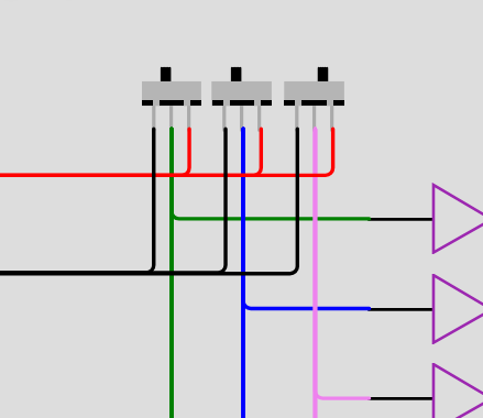
Am I short circuiting the positive and negative when the switches are to the left?
yes
@myzstral
fast way to fix
in diagam.json
fast way to fix
in diagam.json
search and replace
with
in the connections section
then change
to
i've gotten half decent editing the json, easier than removing / re-adding wires 😉
binary decoder arduino 0001 - Wokwi ESP32, STM32, Arduino Simulator
Run IoT and embedded projects in your browser: ESP32, STM32, Arduino, Pi Pico, and more. No installation required!
why does it glitch out, even with arduino?
like it skips the 3rd segment and stuff
check the wiring carefully, I used this as a guide https://www.tutorialspoint.com/digital-electronics/digital-electronics-decoders.htm
to start, this is no good...

some of the glitching is due to a lack of an enable input, mostly it's wiring
I have a working example, let me know if you'd like to see it
(wish there was a quad input AND gate, really stacking the 2 input jobs 🙂 )
Sure
this adds another AND gate to enable / disable the outputs to prevent glitching and uses bit shifting to shuffle the A B C bits https://wokwi.com/projects/436657000602027009
more than one way to skin a cat 😉
@myzstral i omitted the resistors for clarity, in a real circuit each LED will need one
pretty sure i'm not gonna need that when i switch to irl components tho
i'm gonna switch soon
for now
i rewired
and i can atleast
see the things working
( with a bit of glitching but meh )
since i have 9 digits
i'm unfortunately going to have to
make another multiplexer
for the digits
( i love my ideas - sarcasm )
thanks to my geniusness of adding 3 switches which werent necessary
i dont have to wire for 30 minutes again ;P
i love copy pasting
i know i should have used NAND gates instead of sending AND through NOT ( which is the same thing ) but i was too lazy to wire everything again
i'd be interested to see the project link
here's a bodge to get the 3 to 8 to count up (what's one more AND gate)
https://wokwi.com/projects/436784374695414785
Same as the previous link, i update the same thing.
I dont understand why my code works in tinkercad but not in wokwi lol
not sure why the switches are still there, but they need to all be flipped down
then it starts to work but the patterns are all wrong, not sure why, the lower AND gates seem like they are wired correctly
It works better if i disconnect the other 8 digits and ground the single digit, but it seems there is a logic error in your code
Worked in tinkercad but i'll check
maybe a link to your project would make the fault finding a little quicker.
I had sent it
But sure will resend
binary decoder arduino 0001 - Wokwi ESP32, STM32, Arduino Simulator
Run IoT and embedded projects in your browser: ESP32, STM32, Arduino, Pi Pico, and more. No installation required!
I unfortunately cannot pin it
@𓆩𝖒𝖞𝖟𝖘𝖙𝖗𝖆𝖑𓆪 please fix your user name
you can type it as
@myzstral and it pings me
also i'm not aware if it's against the rules
let me check
rule 9 and 3, got it.
its fine if i change it in just this server, right?
well now i've gone through all the rules, i guess.
ah sorry i couldnt update the project
exams are coming and i am busy nowadays
im looking forward to continue the project again once i get my hands on hardware components
got caught up in a software project
abandoned ( for now )
will try to continue soon