ili9488 SPI display not turning on / displaying anything
I'm trying to use an ili9488 tft spi display with an esp32, using platformio and TFT_eSPI. The screen doesn't turn on, and if I connect the backlight to 3v3 it just flashes a bit and then stops.
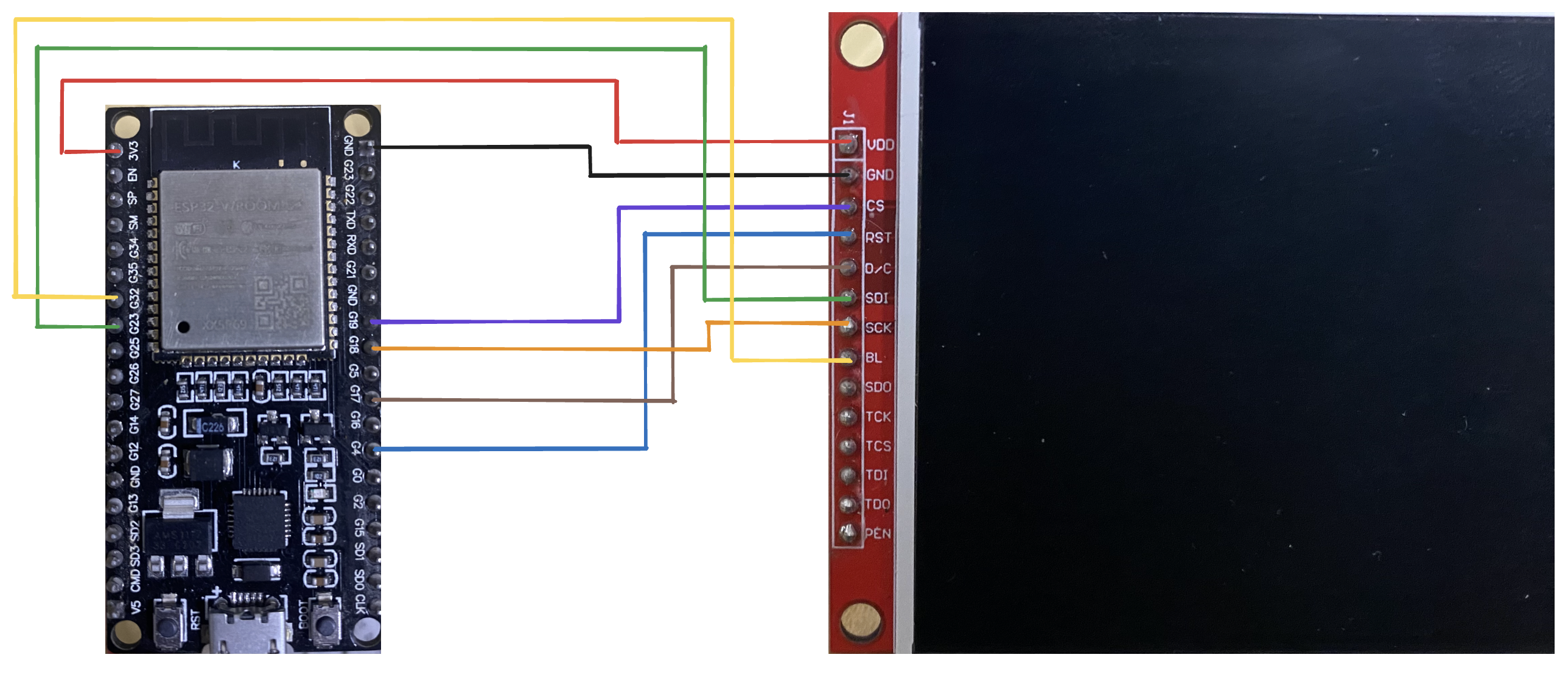
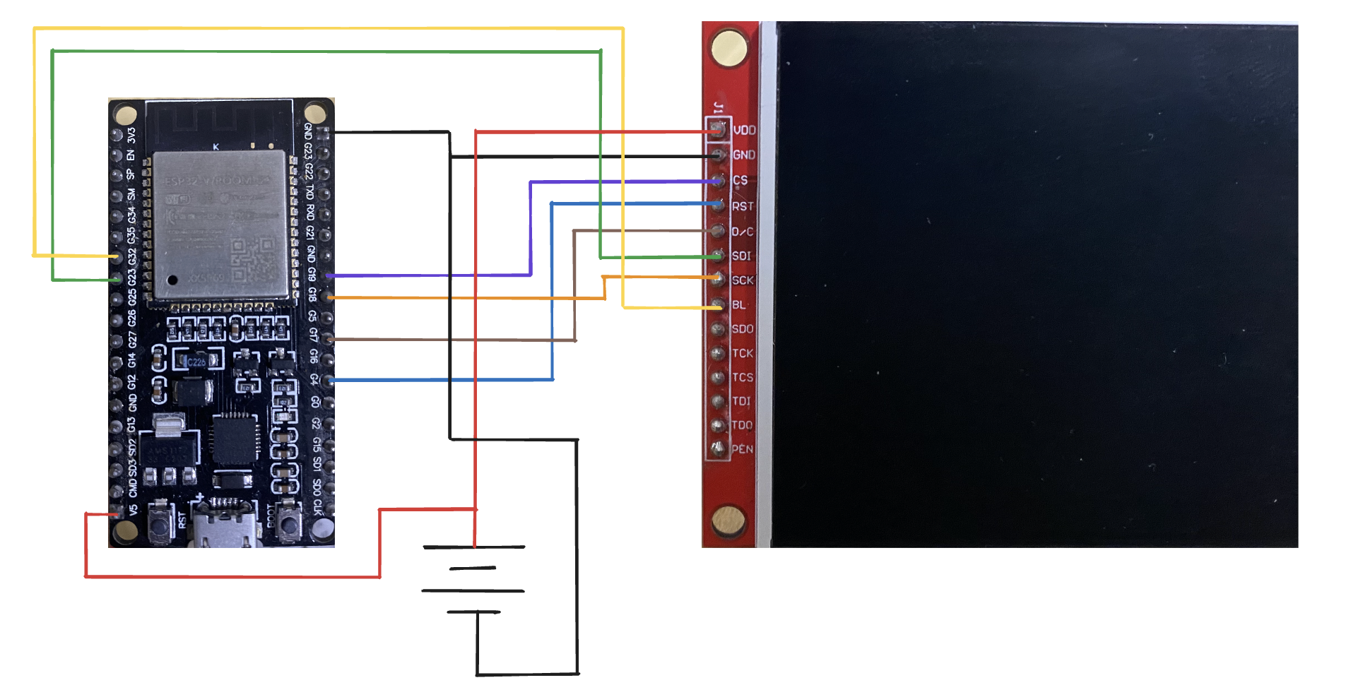
my connections are:
pin definitions in User_Setup.h:
main.cpp:
please try to find what I did wrong.
106 Replies
thanks for moving this, I'm not sure how to help but some smart person will see this thread eventually
and also all wired have been checked with multimeter.
help 😭
this came up on the Wokwi server, maybe ESP32 version 3.0.0 is causing issues
https://github.com/Bodmer/TFT_eSPI/issues/3355
but I am not getting a compilation error, the screen just doesn't display anything
Why is there not a CS wired up?
Heres the.. 349 page manual for the chip 🙂 https://focuslcds.com/wp-content/uploads/Drivers/ILI9488.pdf
oh bruh i forgot to write that
it's connected tot 15
Alright. No MISO needed on this SPI connection?
don't think so, I have tried connecting it and still nothing happened
Its a two-way communication protocol, usually you would wire it all up.
generally you don't need to hear what the screen has to say
Have you tried connecting another SPI device to those pins and seeing if the SPI communication is working?
uh I don't think i've got another spi device
do you see a file called
Processors\TFT_eSPI_ESP32.h?yeah
try adding these lines to it
at which line
any?
i'm just going by what folks on Wokwi are doing to get TFT-eSPI working once the esp core was upped to 3
all they wrote was "add these lines"
i'll just add it to the start, we'll see
it came up because old projects stopped compiling
unfortunately nothing happened...
i have no idea what's going on
maybe my display is just cooked?
but it worked before
also
but again, don't know if this is just a rabbit hole 🙂
that's basically what I have
does it work with the Adafruit library?
ili9488 is not even supported by adafruit gfx
ahhh
well there are some unofficial libraries
idk
When was
before? What was it wired to?
What changed?it was so long ago like 2-3 year ago
hardware didn't change, same esp32 dev board and same display
But new code?
yes.
And new wiring?
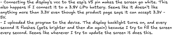
and if I connect the backlight to 3v3 it just flashes a bit and then stops. what does this mean... flashes a bit.. Can you take a video?yes
i will have to charge my phone i'll be back
btw it seems really inconsistent. now the screen is not turning on even with BL to 3v3...
i really have no idea what's goingon
@Tuuli 🎹🎸🤘
Cant really tell if the only LEDs flashing are on the ESP32?
Those might be the comms lights.
they flash when I press the reset button.
And only on the ESP32 now, right? Nothing on the display?
You can check if you have used ESP32 pins with LEDs in your datasheet. Some pins have them, some dont. It also might just flash on reset as part of the reset/bootloader.
I'm pretty sure it just is like that. my esp8266 also flashes on reset with nothing connected. probably to let you know that it reseted
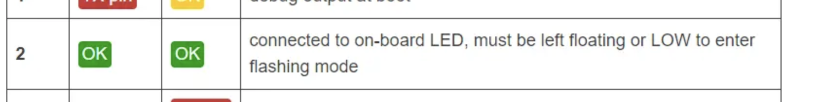
hmm, pin 2 says this
and I am using pin 2 for D/C
is that an issue?
only esp nothing on the lcd
Sometimes the LED pins dont behave like other pins, so yes it would be a good thing to look into whether its an issue or not.
I will try moving it to another pin,
Sure. Or research about it and see if your use matches the things that are problems or not.
Like I said, I can only point you along in general workflow and some logic / experience with troubleshooting, as I'm not familiar with your exact hardware.
okay, here is something weird. After I press reset the screen goes black, but I have to wriggle the usb connector a bit and the screen backlight turns on.
?????
Alrighty. What do you think it might mean? Get curious.
my only guess is a bad cable.
Thats a good guess.
but it flashed perfectly fine
Bad port also comes to mind.
I will try to find some more just in case
could be a faulty usb on the esp too
Too much power being drawn through the port also comes to mind.
yup
External power is always a good thing on a project. Check the power on that display board too, you can fry your ESP32 pins if youre running too much power from them.
I can confirm it's not the cable; I tried two different ones and still the wiggle
sorry but wdym by check them
hmm, I tried another esp board and now the backlight lights up but the screen still isn't showing anything
flashes the screen when I try fill the screen with red, but no red
tried lowering SPI frequency and nothing happens
If I connect vcc to 5V, the screen turns white
I mean check the power rating; how much does the display draw? How much can the pins supply?
for logic 3.3v, for vcc it's 3.3 - 5v, and power is 90mA
Is that for the ESP32 or your display? And how about the other side? Are they compatible?
Also, not sure if this is your first project or what, be very careful with 3.3V logic devices - they will be fried if you connect their pins to 5V logic devices.
what I just said is for the display, the esp is 3.3v but it can take an input of 5V because of the voltage regulator
not sure about power
power and logic levels are two different things
many devices can be powered via 5v, but the pins may only be safe for 3.3v logic levels
esps will not tolerate 5v on pins, the same may or may not be true for your display
the display can take 5v for vcc and 3.3v logic as I said before. as for the esp, the input voltage (for power) can be 5v (if you connect it to 5v pin or usb) but the logic is 3.3v only. as far as I know, I don't think there's an issue here.
Sounds ok...
Hmm.. Its not clear to me if you are following a solid troubleshoot process with this and just keeping it private ie not sharing with us here? Would you like some tips on troubleshooting best practices?
sure, tbh i am not really following any process and I am just trying stuff and seeing if it works and checking datasheets
Ok. That works, as long as you're taking notes. That's the main tip. Write a little project file that lists:
* all the parts
* their datasheets
* purpose
And then as you try things:
* notes about things you are observing as you try different ideas.
* Include code
* Include simple wiring diagrams showing exactly what the hardware is setup as, for that observation. Voltage measurements of power are useful if you have a multimeter
* what you see/hear/smell - try to use quantified and specific observations as much as possible. It might not mean anything to you now, but as you learn more and read others reports, you will start to notice patterns.
Also good is reference info:
* Links to tutorials, blog posts, youtube, etc
And finally some learnings / notes for future. Things like "I learned to never measure current across voltages."
I think I discovered something. I removed the wire connecting the esp's 3v3 to the display's vcc. Then I put a multimeter between them set to dc amp mode. it only read 9.5 mA, when the display wants 90 mA. I might have made a mistake but I think this is the problem.
accidentally shorted a battery, it went sparky sparky 💀
Things like "I learned to never measure current across voltages." did I jinx it?I didn't understand that I'm sorry 😂
wdym by across voltage
btw do you know how I can fix it not having enough current?
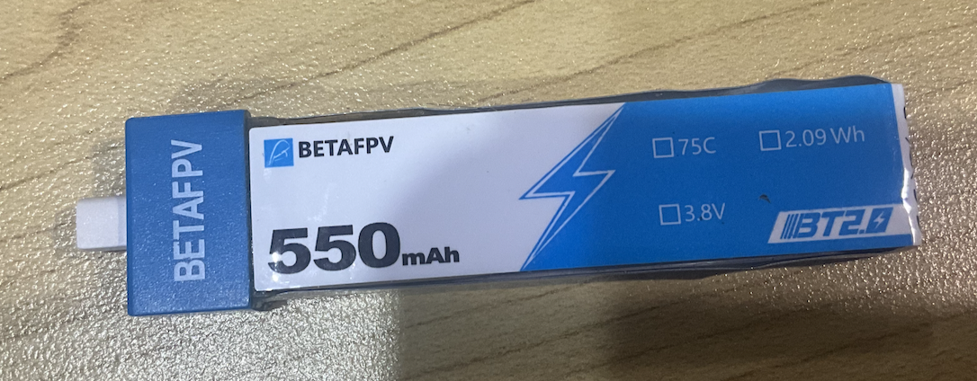
will try connecting battery directly to display.
it turned white...
Um. Draw a circuit diagram please. Connecting the battery directly to the display will only work (and not break things) if you mean that you checked the voltage and its ok.
Across voltages. When you measure amps, its a short circuit - the meter lets all the current flow, and measures it.
I am guessing thats what you did with your battery - left the meter in Amps mode and touched both terminals.
I'd really recommend just watching a few electronics tutorials on the basics, so that at least you arent breaking your equipment or the hardware.
How are you powering it? You need to post more information here, noone on this end knows much about whats happening other than its not working, its an ili9488-based board of some kind, and it sometimes turns white 😄
will do. sorry that I’m not sharing as much as i’m trying stuff, as its hard for ppl to help if i don’t, especially if u are not familiar with the hardware im using
sure
it might take me a while but i’ll get back to you with a circuit diagram. thanks for taking the time trying to help this idiot 🙃
Yup exactly. It will help you too! But yeah... you cant really ask for help with something and expect useful responses if you don't describe everything, and work with the people helping you, answer questions, try things that are suggested, etc. The amount of help you get is usually proportional to how much and how clearly you communicate 😄
Learning to get help is a useful skill too though 😄
@Tuuli 🎹🎸🤘
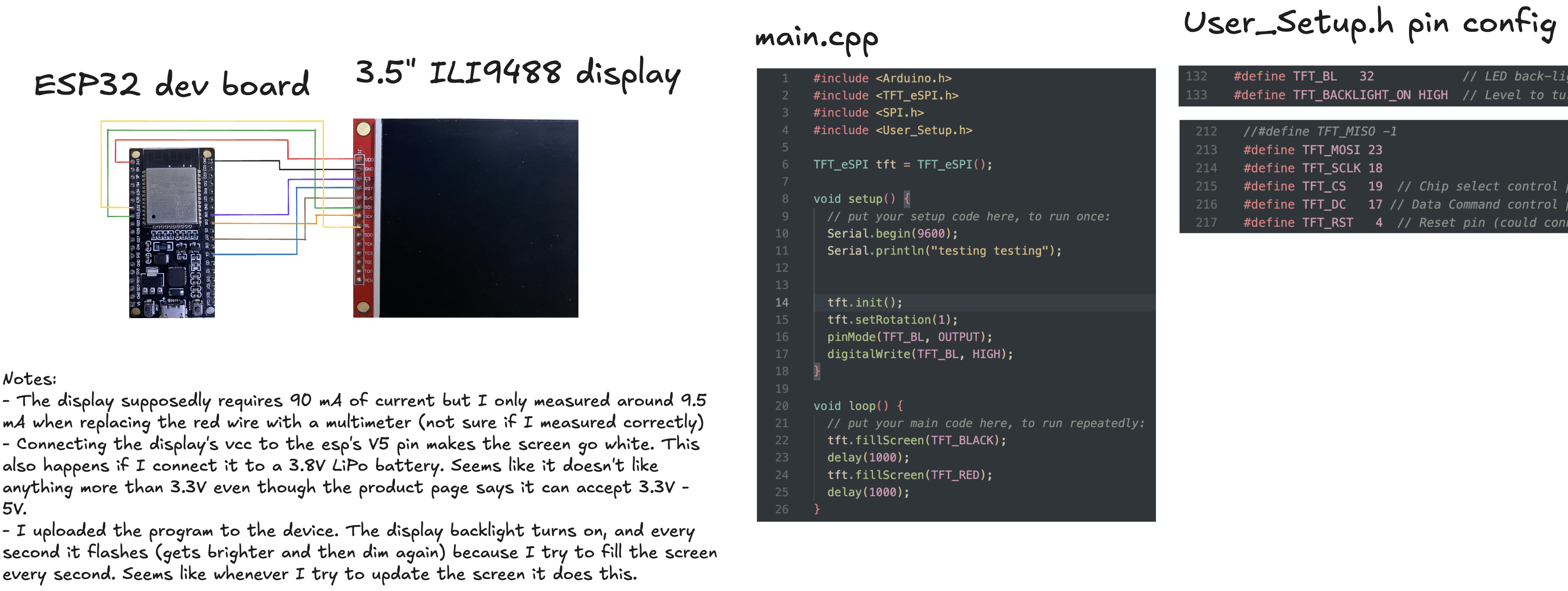
I take the 90 mA thing back, I think that was the total power consumption of the screen, not how much current it wants through vcc.
idk
Nice, good job on that. Its all powered through the USB on the ESP32? Also do you have a datasheet for the screen and for the ESP32?
Look into the difference between TCS and CS. The datasheet (or tutorials for similar displays if its a knockoff-undocumented-ebay deal...) will help you understand what all the pins are supposed to do. I assume you're using jumper wires, the wires aren't still soldered from years ago when you had this working before?
no, they are generic boards from ebay
yup. jumper wires. all of the ones that start with T are for the touchscreen SPI, which I am not using.
and yes it's powered thru usb for now
Ok. How do you know that, what references are you using if there's no datasheet for this particular board?
Also where are you connecting the battery "directly to the display, and it turns white", and what battery, and what voltage is that?
I'm only assuming because there is little to no information on the specific board. I remember when I used this in a previous project I did not have to use those.
it's was a little 3.8v drone battery I had.
apple image formats 🤦♂️
Hmm. I'd research that if I was you. Find references for similar boards.
"I remember how the pins connect" - been there, been wrong 😄
I'd also suggest you add the battery to another connection diagram, show how its connected.
Remember when you add an external power source that you need to tie the grounds together.
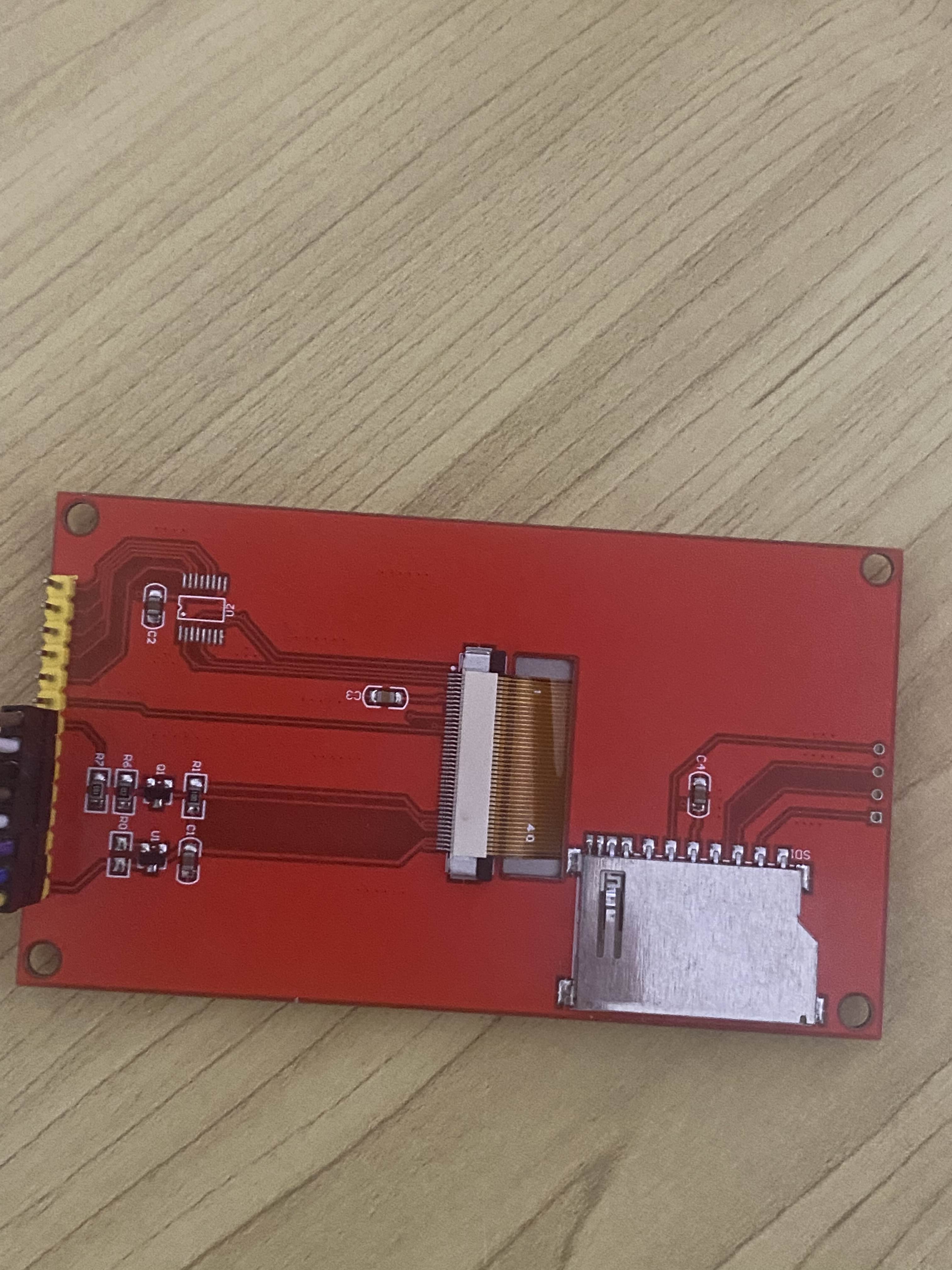
Oh and you can photograph the back of the board and include it in your notes.
Does it look like this one? https://www.youtube.com/watch?v=NidjZOxMMxo
Saravanan AL
YouTube
3.5" TFT Color TOUCH Display-DRIVER ILI9488 for NodeMcu ESP32
ILI 9488 driver enabled 3.5" touch display 480x320 Resolution .suitable for Nodemcu & other 32 bit controllers like ESP32, STM32 ,RP2040.
buy link :
https://www.alselectro.in/product-page/3-5-tft-480x320-color-display-for-nodemcu-esp32
Matching Library is TFT_eSPI
https://github.com/Bodmer/TFT_eSPI
Download the zip file and install it in Ardui...
Is the screen white like in this video? This implies that its white when it has power but not data. Or not correct data. https://www.youtube.com/watch?v=8UDEl8uBU7M
Imperio Sheriff
YouTube
How to make working the SPI TFT ILI9488 on ESP32
TFT_eSPI library: https://github.com/Bodmer/TFT_eSPI
The pin connection used in this example is:
TFT_MISO 19 // (leave TFT SDO disconnected if other SPI devices share MISO)
TFT_MOSI 23
TFT_SCLK 18
TFT_CS 14 // Chip select control pin
TFT_DC 27 // Data Command control pin
TFT_RST ...
looks like neither of those
Cool beans.
If you want help, just go ahead and ask your questions.
unrelated to the display but what do you mean by this?
One ground, all connected on everything. Battery, display, microcontroller.
Research some beginner electronics tutorials if thats still not clear 😅
in many aspects of electronics (and life) it's best to start from a common ground
oh, I thought u were talking about something else nvm
i don’t have anything to ask, it just doesn’t work and I still don’t know why. I will keep trying
Alright. Well if you want some help, you should do some research. Share what you are learning here. Like if you find a similar YouTube or Tutorial video, you can share it. Update your notes about different things you've tried, and share those. Share your code.
I suspect that if you connect the battery so that it's independently powered (like you did before when it turned white); connect the grounds properly; and put the correct code on your ESP32 - that might do it. Either that or its broken.
like this?
Other than tutorials, things you can look for are "test code" "basic code" "one pixel code" "all red code" - you get the idea. Just REALLY simple tests. And references for wiring for similar boards.
Yeah! Um one thing though, what is V5 pin?
You have a 3.3V battery right? Is that a 3.3V pin?
Do you have the datasheet for your ESP32? Thats where youll check that.
Another term is the "pinout diagram"
as far as I know, it's a power input pin that can support 5v which gets converted to 3.3 by the board
and I am using a 3.8V battery so that's why I am using it
Hmm. I recommend you check that before you turn on the battery. If you already have checked the datasheet and what that pin does, but just didnt share the actual research / source for that; then that's fine. But you'll get better help if you share more here. Certainly from me. Others who own this hardware might have such things memorized.
on other boards it's labed VIN
Ok. As long as you checked on the datasheet what voltages it can accept.
Is this still whats happening?
that time I was connecting the battery to the esp32 only. I will try both the display and the esp tomorrow
Great. Let us know how it goes.
I have looked it up and I think 3.8v is too low for the voltage regulator chip on my board to provide 3.3v. maybe that's why it's called v5 🤦♂️
Could be. Yeah Vin on my Nano needs at least 7V https://docs.arduino.cc/learn/electronics/power-pins/#vin-pin
what do you suggest I do now? maybe I could ask somewhere else?
Sure. I have no further suggestions beyond everything I've already suggested. Research similar boards, compile all the research and information about the hardware and software, learn what everything does and what it's supposed to do.
And for testing, test everything separately. I guess another test you can do is checking if your pins work. If you have a multimeter, disconnect them from the display and turn them to 0, 1 and measure the voltage.
would the arduino reddit be good? I really can't think of any other places
Or arduino forums perhaps. Or you can try searching inside this forum and see if anyone posted here about TFT displays
Or you can ask the mods if its ok to bump your search for someone to help.
(As you know, I can only provide general ideas since I dont have this hardware - perhaps someone with experience with either the ESP32 or the TFT display can help more)
I looked through your past messages too and I see you are using platformIO for this. Maybe that makes a difference too.
And maybe if this is your first platformIO project you can do a beginner Blink project first instead. Always start with the simplest thing.
I also see you telling people this used to work in Arduino IDE. But you arent trying that here?
i am trying on arduino now.
This board is abandoned by OP now, thread can be closed.