ATS2855
Hey
Does anyone know anything about the ATS2855?
I got a chinese gaming controller and need to dump the firmware from the chip
(the controller has 4 buttons on the back, 2 back buttons and 2 to programm them with other controller buttons. and i wanna try to make them work as normal buttons instead, via firmware if possible)
All i can find online is:
" ATS2855 has many rich interfaces, such as SDIO, SPI, USB2.0, UART, I2S, PWM, IR, TWI, etc."
"ATS2855 is a Bluetooth controller component, which supports Bluetooth Ver5.0 dual mode. It supports dual mode (BR/EDR/LE), and the links in BR/EDR and LE can be active simultaneously."
There are only docs/datasheets for the ATS2825, 2835 and 2853
94 Replies
This is from the 2825
Help
ok
I see
Hi
ATS2855 | JLCPCB Assembly | New Arrivals | JLCPCB
ATS2855 from JLCPCB Assembly - New Arrivals is available for JLCPCB assembly, check the stock, pricing and datasheet, and let JLCPCB helps you assemble the part ATS2855 for free.
Controller that has the same chip
https://device.report/actions-technology/ats2855
https://www.amazon.com/Controller-Interactive-Joysticks-Programmable-Compatible-PC/dp/B0F83TRDD2
simlar controller (same SoC) but that one has a display

It gets recognized as an original dualshok 4 over usb-c
Even hardware id and stuff
And model number
interesting
ps4 clone
But if i hold the options button on power on it gets recognized as switch pro controller
Also with the right hardware ids and stuff
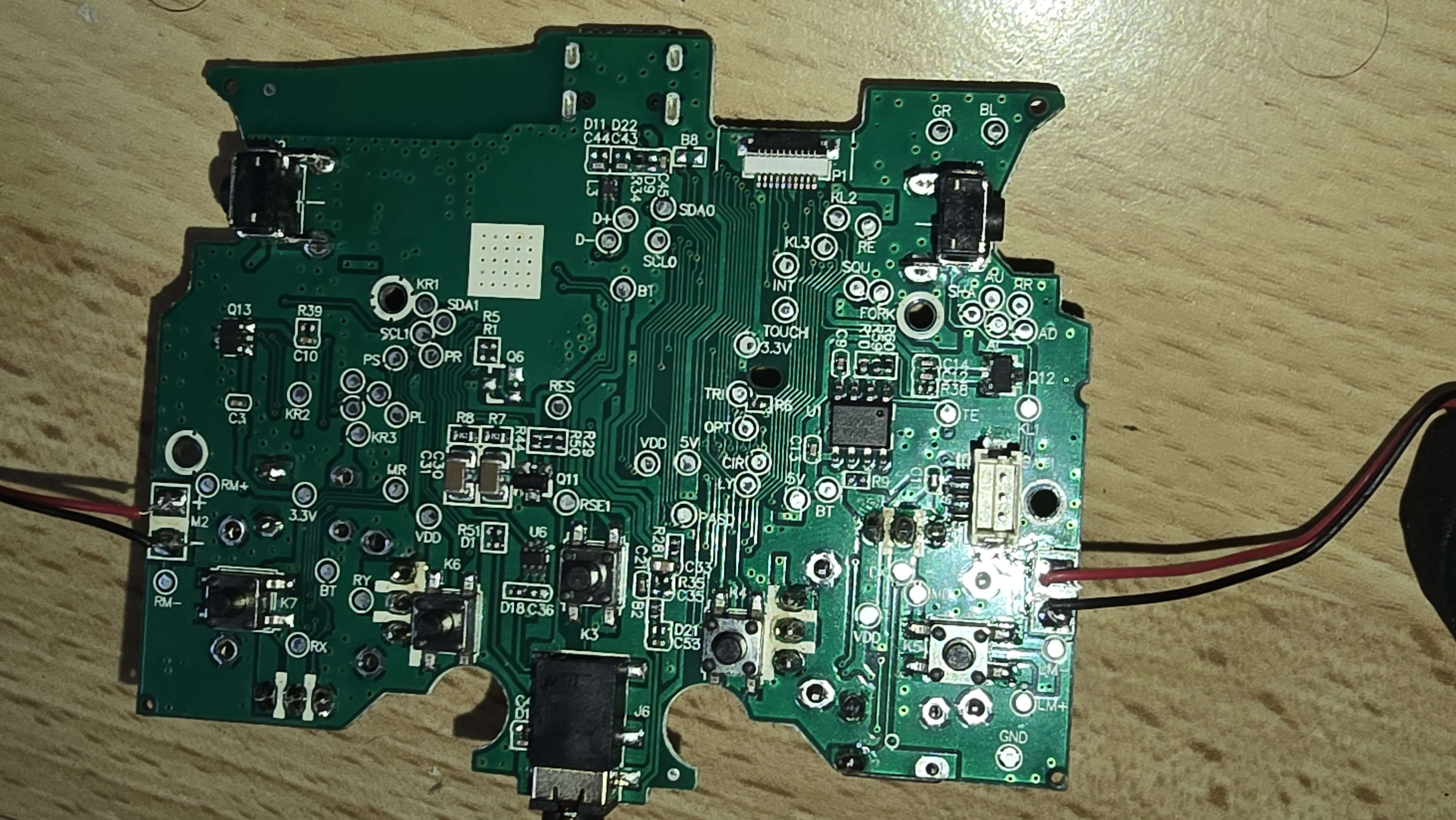
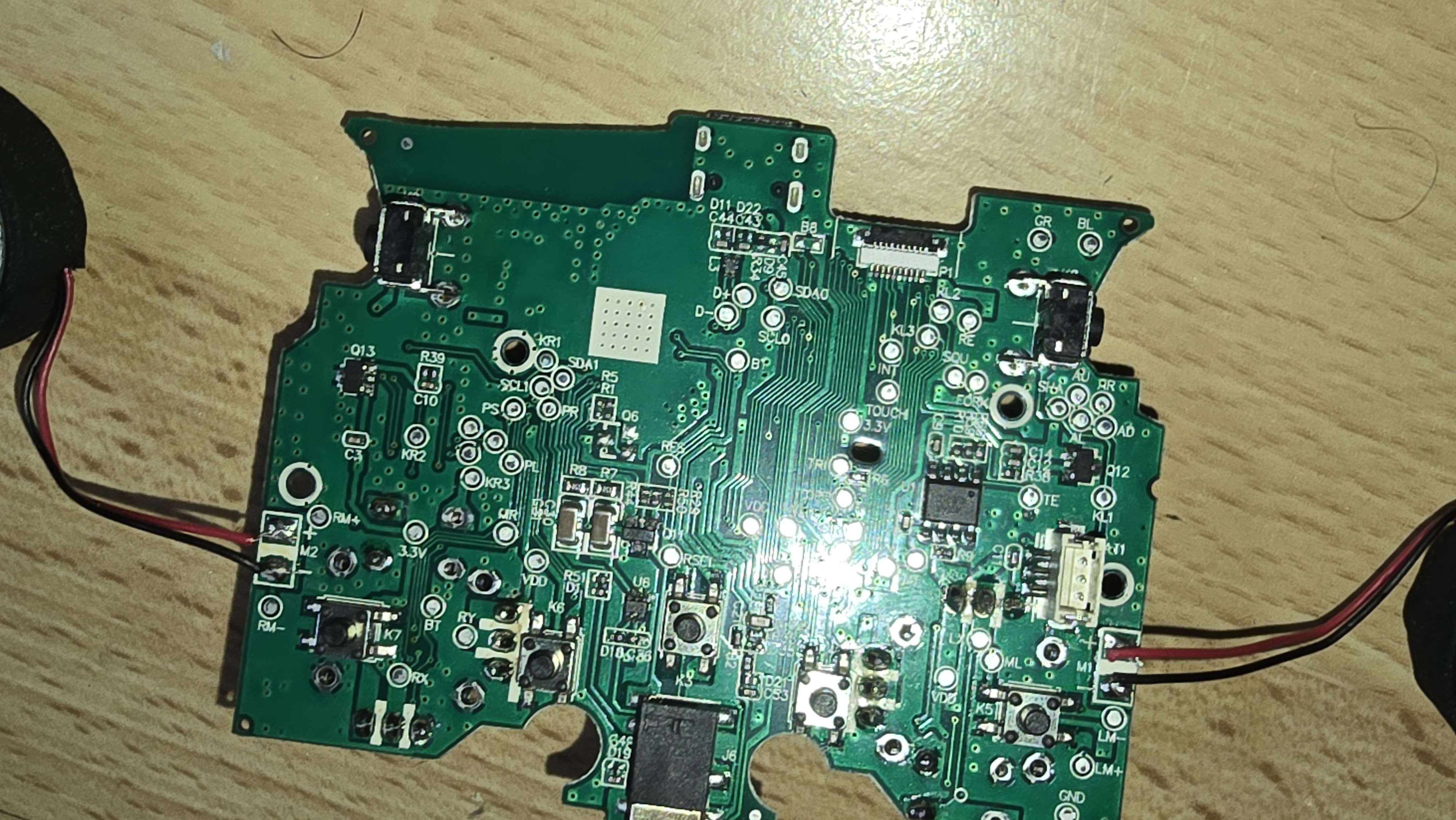
I am trying to relate u4 to the ats2855
now that is odd
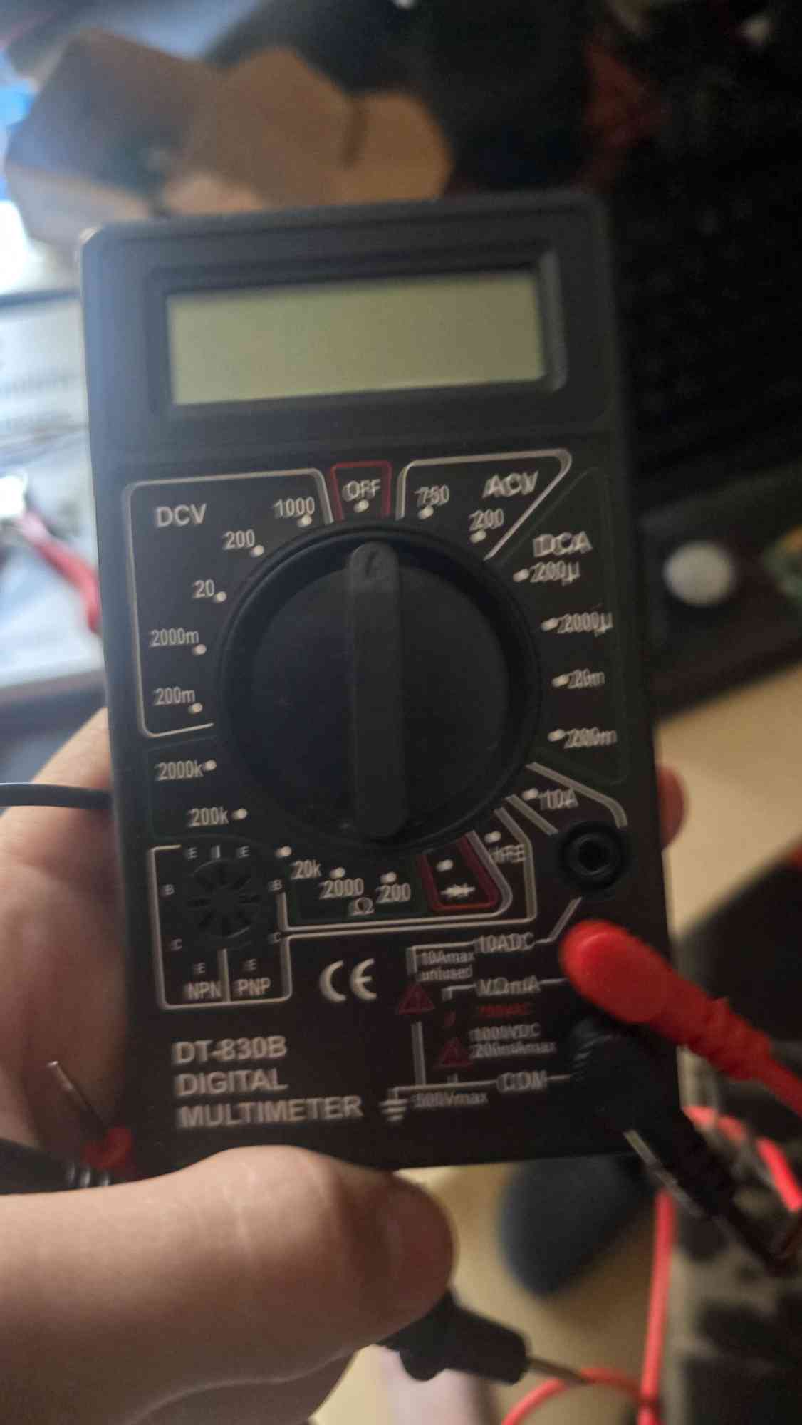
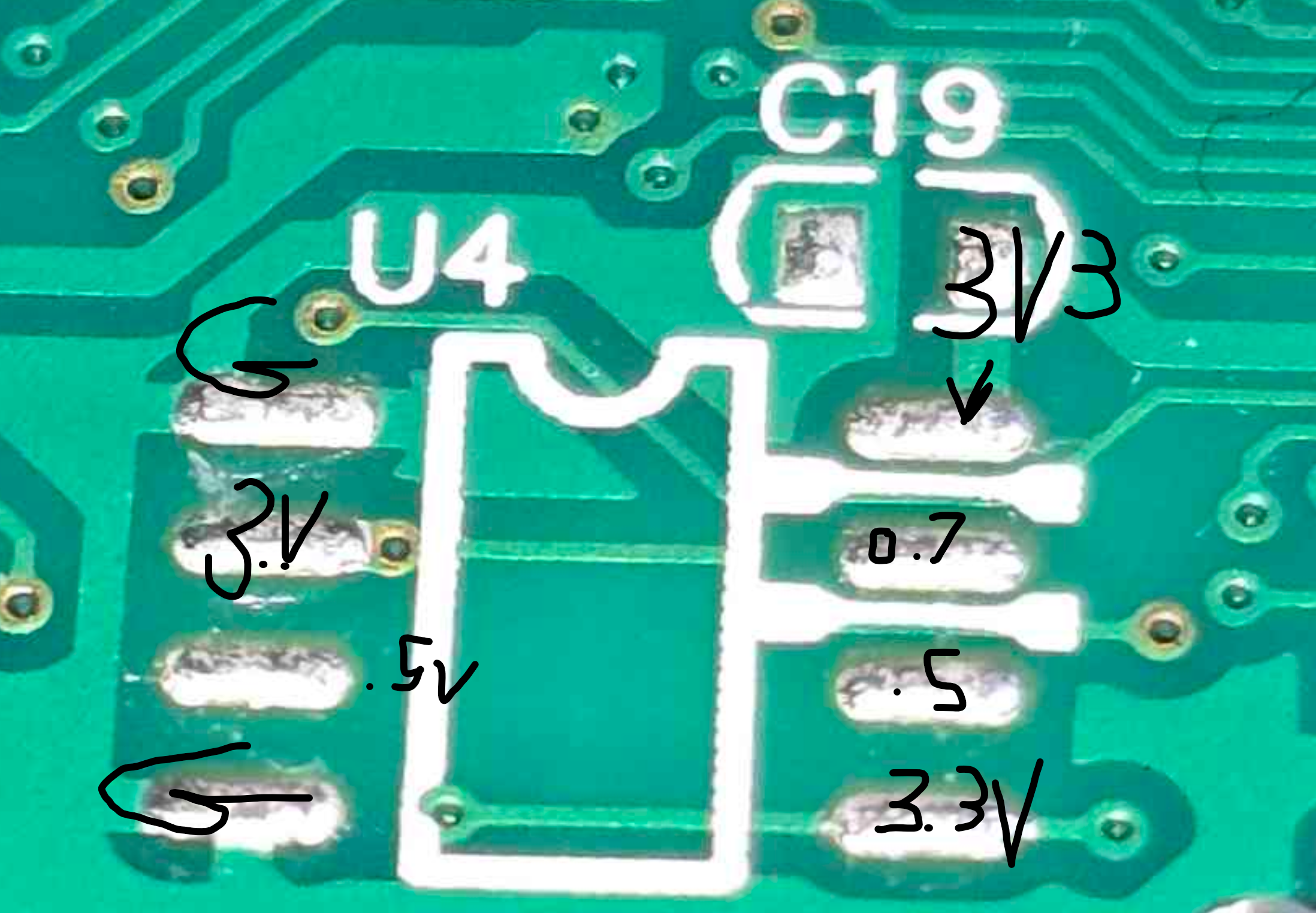
So any way, you'll need to see where the lower volt pins go
If I had to bet, the two on the right go to the 2855
The reading ont he left is odd. I wouldn't expect to get 3 3.3v pins total
Fake vs Original Xbox series Controller Chips / motherboars? : r/XboxSupport https://share.google/v2Q49tKc6ZZRjFZpc
Reddit
From the XboxSupport community on Reddit: Fake vs Original Xbox ser...
Explore this post and more from the XboxSupport community
Interesting
This also probably has pertinent data
Instructables
CSR Bluetooth Module Programming
CSR Bluetooth Module Programming: I've made a few Bluetooth speakers recently (links below) and whilst they are great to look at and fantastic to listen to but the "Name" that comes up on my phone (or Bluetooth streaming device) is either:
1) Something boring like "CSR 8645"!
and/…
Hm
Im looking into it rn
But looks realy like a place for optional spi flash (the chio supports externel spi norflash) then uart
Thanks for your help
Didnt get any further
It wont be an overnight thing.
ok
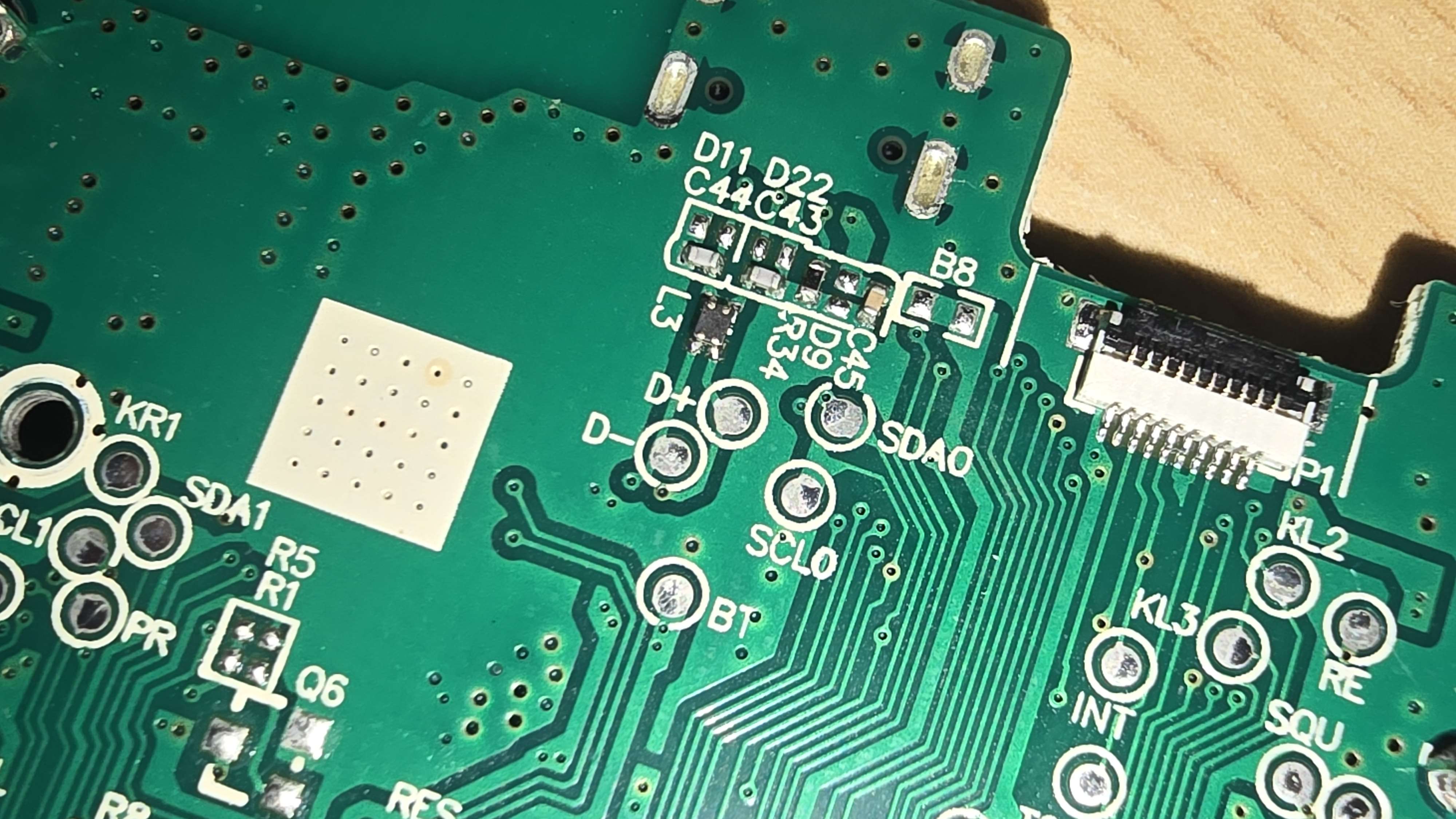
Got data from the i2c pads on the back
But it only gives out 0xFF every few minutes or smth
The controller doesnt have any open uart pads as it seems
never got an email back from the company/?
no
Yeah, I'd have to buy one to be more helpful unfortunately
I could buy you one (the same) but idk how much Shopping xd also you dont realy need to help, only if you want to help.
I think shiping is more expensive then the controller
Xd
A PERSON OF A COMPANY WHO USES THIS CHIP IS ACCTUALY ANSWERING
WRITING IN PM WITH THEM RN
shit
they signed an NDA
the gen 5w
(top one=
currently no firmware, BUT there will maybe be one in the future
and it supports flashing over usb-c
This is great news for you! It's always best to reach out to companies, you never know what might happen
I only got a hint
"Buy the gen5w, maybe Poking around in pin Ball games will help you" (from another worker there)
Is that a hint of Poking around with pins on the other controller that uses the chip too?
I would say you'd have to get the gen5w and pole around the BGA pins that are exposed to you. But that's the best I can come up with
That's as big of a hint as you're gonna get, so if it's relatively cheap, I'd go for it. If it's over 100 USD, probably not worth it unless you have disposable income.
79,99$
just do it, and be careful with it
then get a second if you are really comitted
...
i found another i2c pin
not data again
My guess is they could also mean literally sniffing the board with simple games running to see what happens when you press buttons etc.
hm
Which interfaces are you trying to find pins for?
something like uart or directly reading the internal spi norflash inside the chip
Also you can sometimes find the "service manual" for parts lists, PCB schematics, board layouts, etc.
i couldnt
Depends on the electronics of course. If its Nintendo its not going to be available 🙂
i even searched like 13h straight, no sleep
its a random chinese controller
i dont even need the pcb infos
just infos about the chip
but there are none
Are you sure this isnt good enough?
2825 vs 2855 🤷♀️ If it looks alright when you trace the pins and makes sense with that layout... 🤷♀️
thats a chip schematic for the ats2825, it tried but almost all pins are wrong
gtg
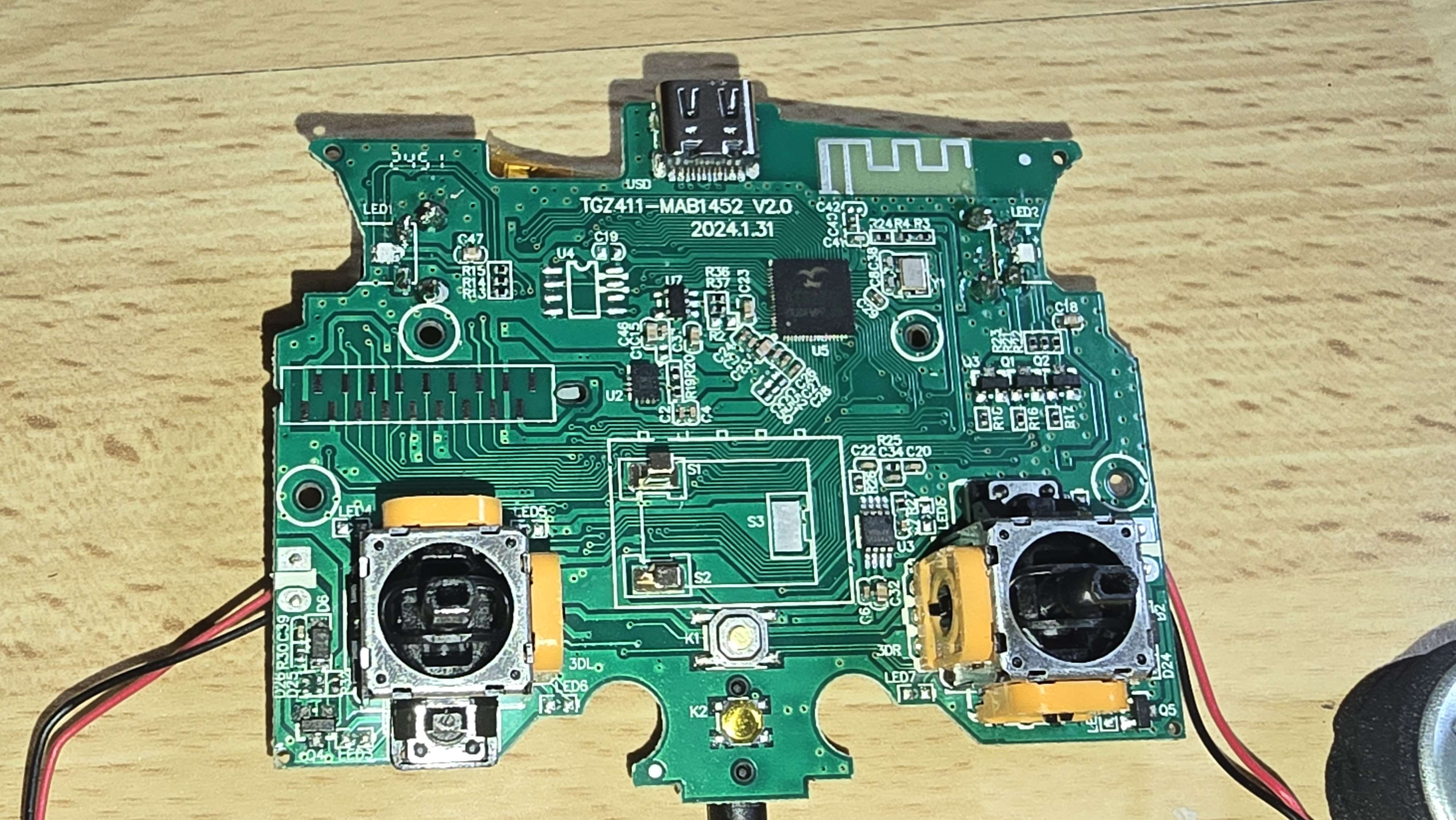
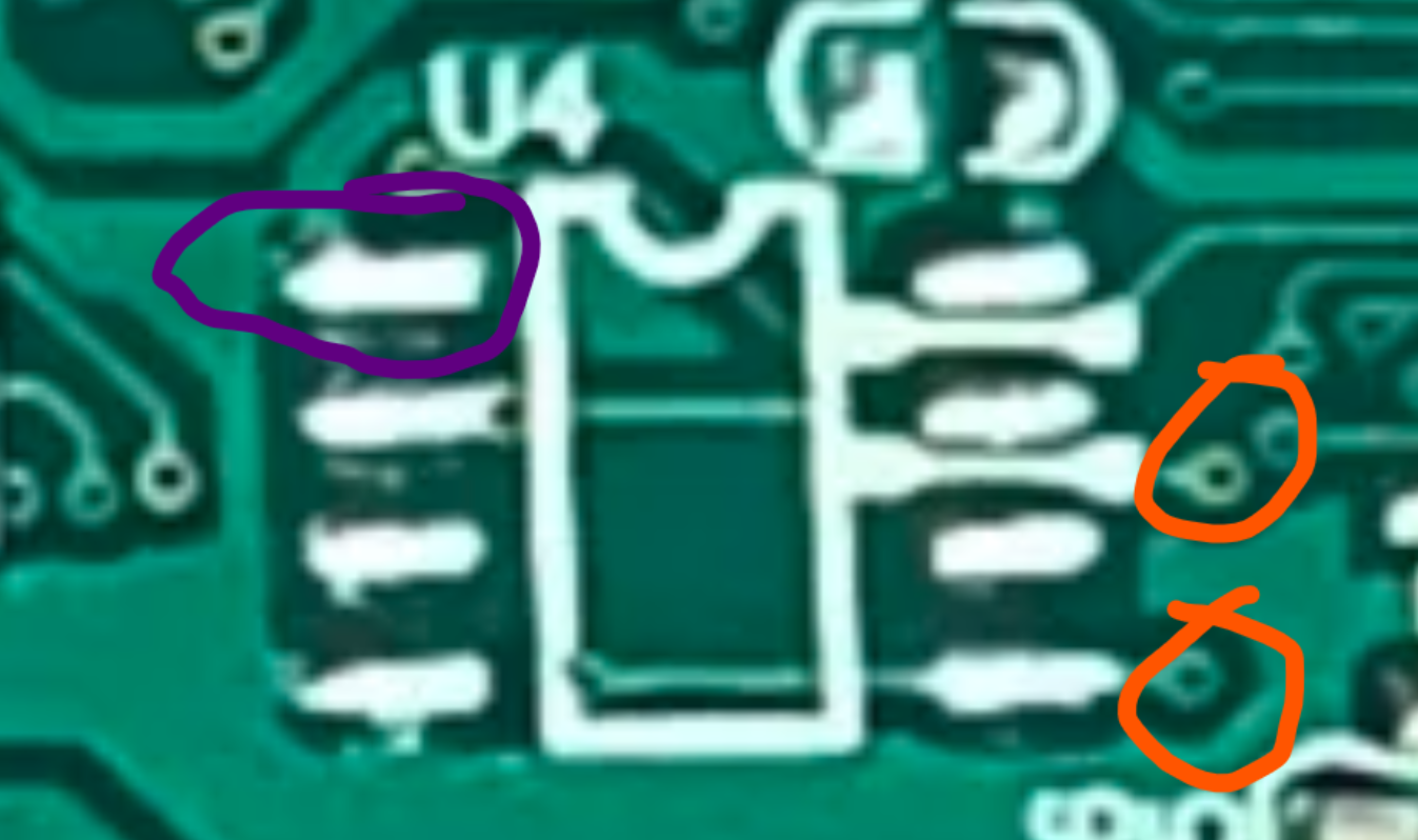
Cool. Id look into what U3 and U2 are. Capacitors on the board are mostly going to be stabilizing power, so tieing the Vcc pins to ground near components; you can use that to trace your ground plane and check with a multimeter.
The little pinholes that traces go to are vias, they bring the pins to the other side of the board. So you can trace them on both sides. A marker can help lol to mark all the power and ground pins.
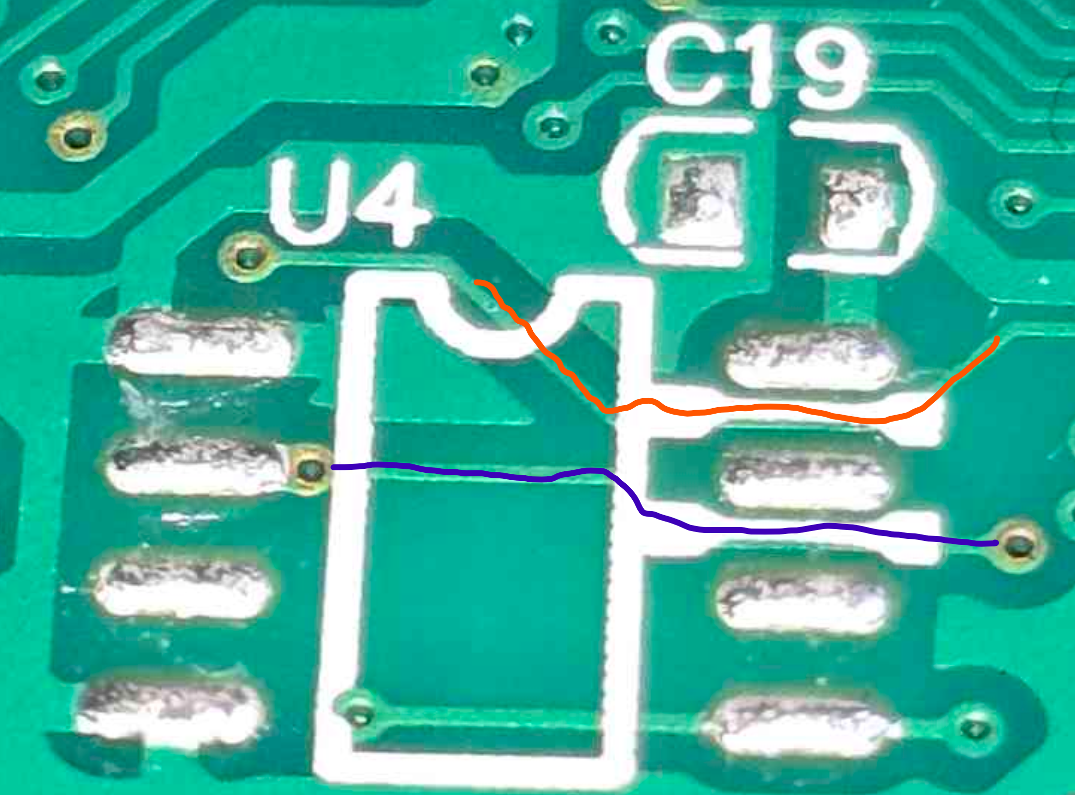
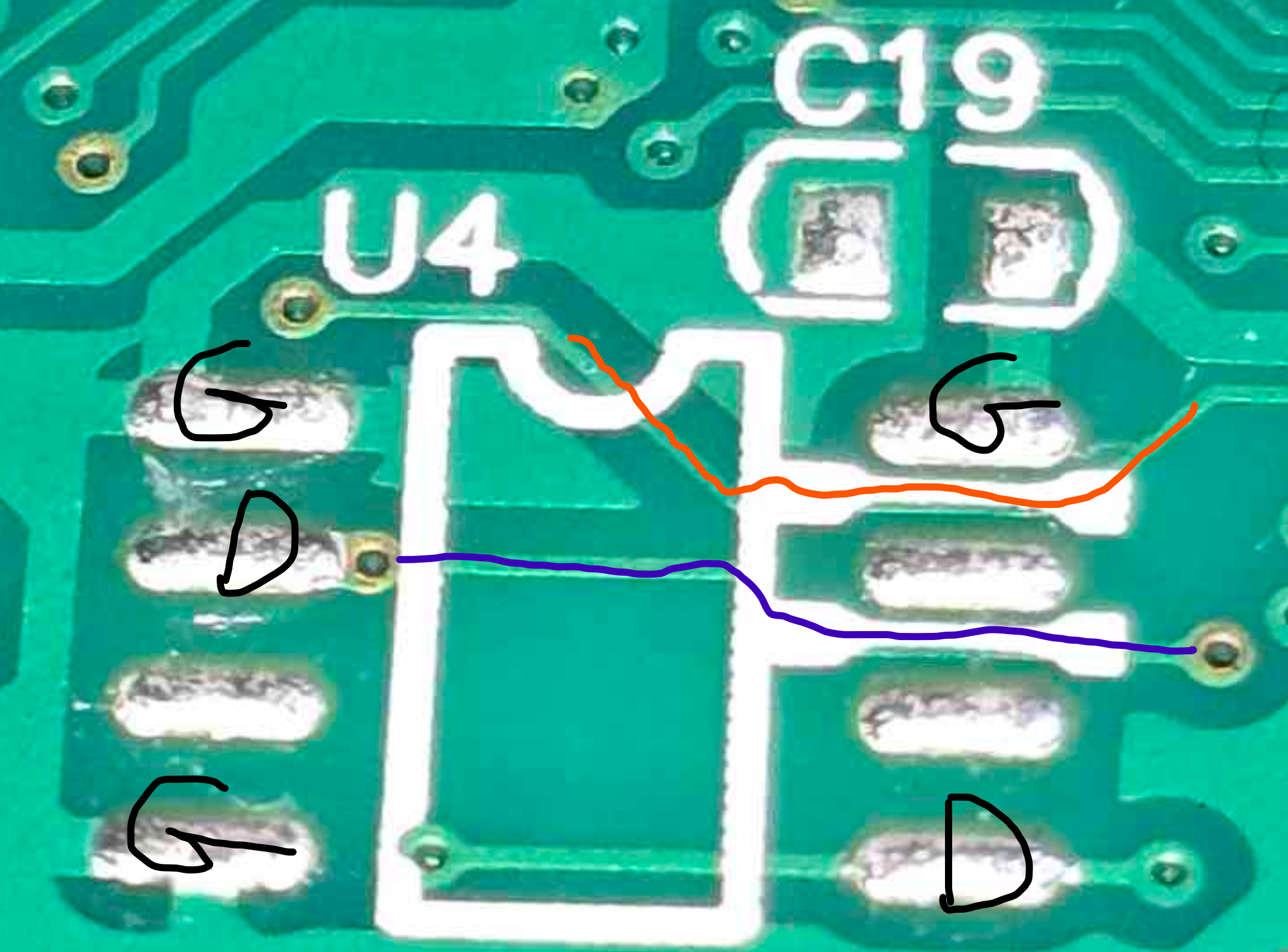
We kinda arrived at the same conclusions. What are your thoughts on U4?
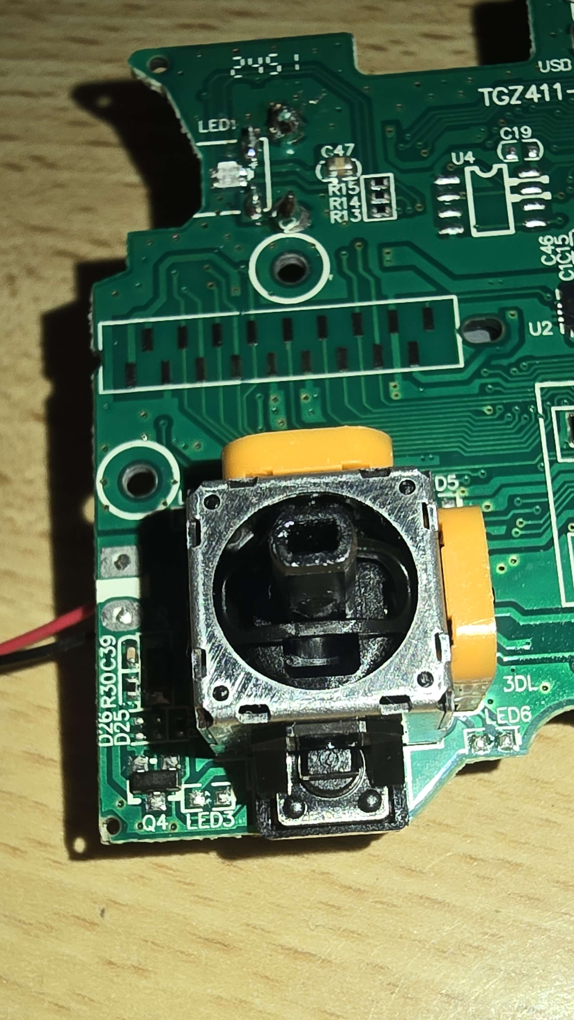
Um. Its empty and Im confused why you are looking at it, honestly 😁
C19 is a stabilizing power cap I would guess. Connects the ground to the power, next to what would be a chip.
Reduces noise and brownouts.
But that part of the circuit isnt in use.
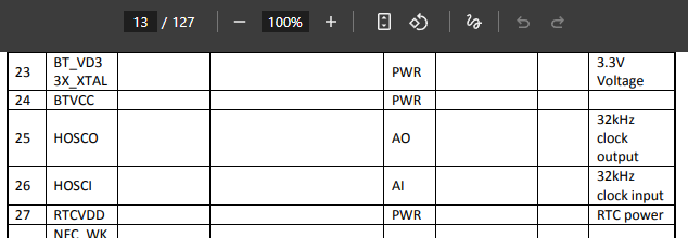
Y1 is an oscillator. In the chip datasheet this is a good landmark. I didnt look at the datasheet but the oscillator pins should be called out.
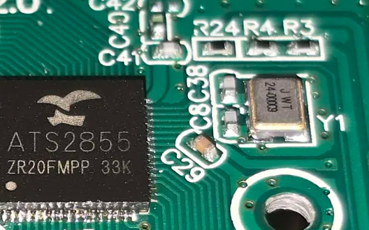
HOSCI and HOSCO perhaps.
In the actual reference sheet for the chip it should be very clear though.
U7 I figured was something to do with the USB comms. I see the chip maybe has onboard UART so not too sure what it might be.
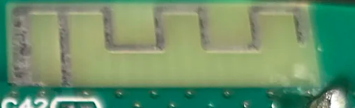
This is the bluetooth antenna by the way. Probably you ID'd that already 😄
I thought it went to some data pins on the main IC
The board does. But theres literally nothing there 🤔
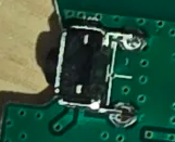
That is a marking on the board for a chip that isnt populated
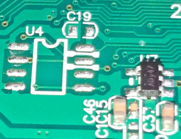
Left - no components
Right - a chip and capacitors
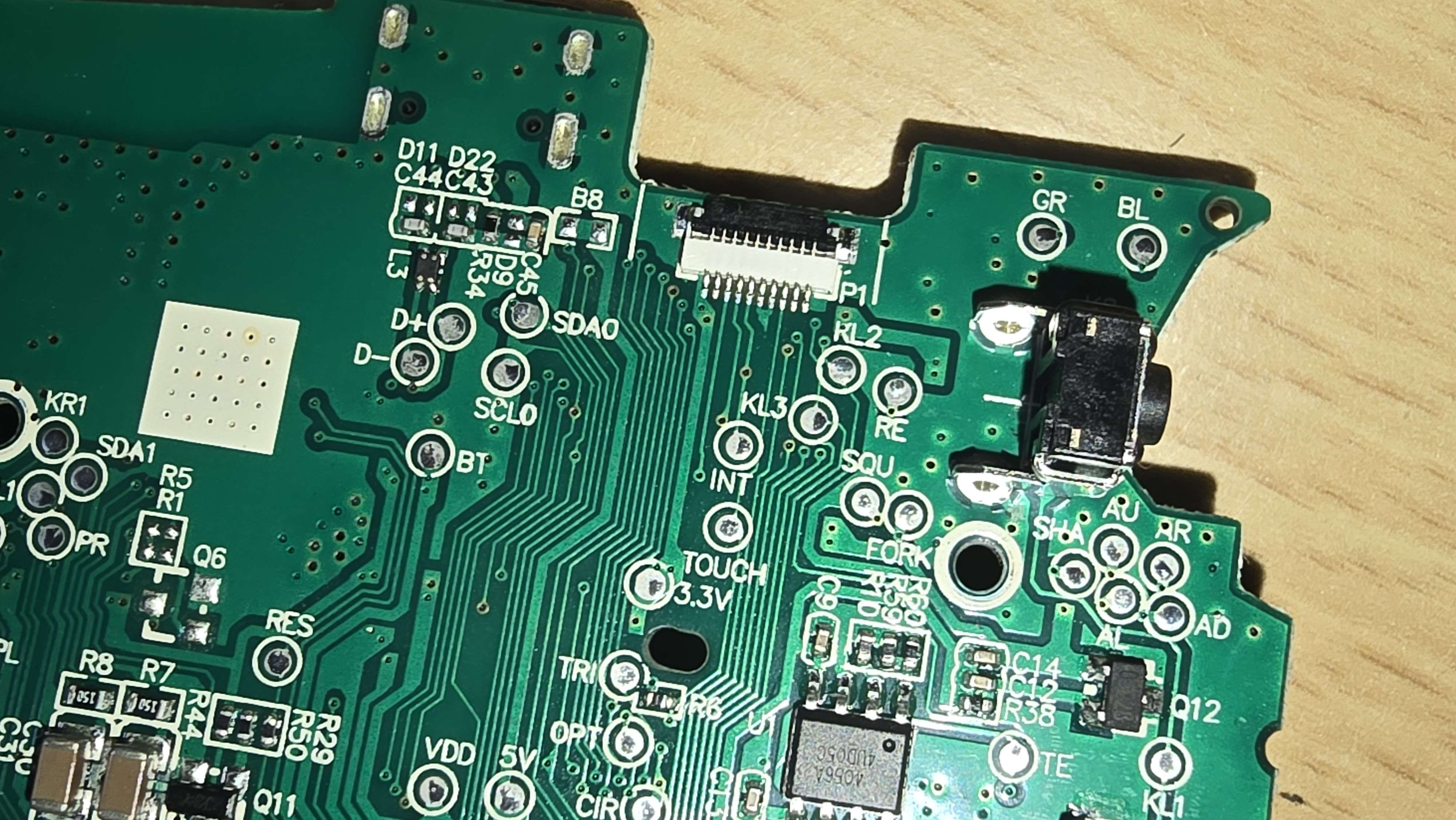
Also this is a headphone jack I believe. So another landmark for tracing
this explains voltage on 3 pins, gnd on 2 and vcc on one
Finding something like this for the same manufacturer's chip would be a good start. This is just a random QFN68 packaged controller I found on Digikey.
But you can see how all the information is laid out, which pin does what, how to use them.
If you have the full datasheet this came from, posting it would help.
Thats a button
Ah gotcha.
https://fcc.report/FCC-ID/2AIGJ1201799/3226008.pdf
But its the ats2825 datasheet
Not 2855
The clock (external crystal oscillator) and the USB pins should be easy to trace if you know what you're looking for. With the help of the datasheet it should be doable to check if the pinouts are the same.
I know where the usb pins are
The controller has a usb-c port
But you cant read any firmware from it
Right. But arent you trying to map the controllers pins?
The ATS2855.
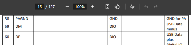
Pins 59 and 60 on the QFN68 are the USB data pins
(maybe.... BUT it would be easy to trace those pins to see if they MIGHT BE.)
Typically datasheets dont change TOO much between controllers in the same series. So pinouts and stuff are likely the same.
I also got the datasheet of the 2853BT
You know where D+ and D- are on the board, and you know where pin 59 and 60 are on the chip. So you can meter them to see if they're connected, and visually trace them to see if they go together.
Im trying to find pins like uart or smth, so i can read logs or even firmware
The way to do that is to map the chip 😄
Okey
Gonna try when im home
Sounds like a plan.
You said though that you'd already looked and found out that the pins DONT match? What exactly did you find didnt match?
Almost all
Can you give an example?
uart
spi
i2c
dont know the numbers
Like in full detail. Im just trying to see if youve already done the work correctly, or maybe you missed something and I can help. “Pin abc on the chip, circled here, should be spi, but I tried connecting and powering on and no data is sent”
If you share what you did exactly then we can help.
i looked at the datasheet of the 2825
looked up which pins where uart
connected esp32 uart pins to them
and tried to read
no output
i tried to read something from the i2c pins specified in the datasheet via an i2c scanner on esp32
no output
only the gnd pin is true in the datasheet
Hmm ok. It doesnt necessarily mean the pins are wrong, it might mean the firmware on the chip doesnt use them too.
no they are wrong because it needs to use some i2c or spi etc.
to detect buttons and stuff
and the mouse pad
(touch pad9
Right. Did you trace the board from those comms pin on the ATS2855 chip, and find they connected to i2c devices in the hardware? Like a button is not automatically an i2c connection, it might be digital IO also. And I don't see any obvious MUX chips or stuff that would DEFINITELY indicate that's how it's working.
Like Adafruit's i2c buttons use an ATSAMD09D chip to convert analogue and digital signals into i2c. https://learn.adafruit.com/joy-featherwing/downloads So the buttons would similarly need to go to a chip in digital i/o and analogue signals to be converted to i2c.
Joy Featherwing
Turn your Feather into a game controller!
There are few enough buttons and enough pins on the QFN68 that I wouldnt be surprised if its all going directly to the main chip.
And like, just building more on the joy feather example, heres the datasheet for THAT chip https://ww1.microchip.com/downloads/aemDocuments/documents/OTH/ProductDocuments/DataSheets/Atmel-42414-SAM-D09_Summary.pdf
Back you YOUR chip (or the chip in the same family...)...
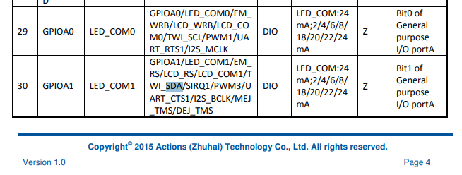
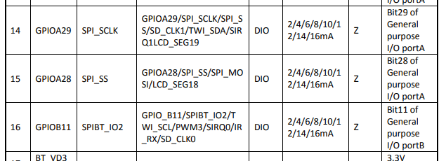
Did you try to connect to these pins on the chip? TWI_SCL and TWI_SDA?
Or these ones?
yes
i tried them all
no in or output
Ok. And did you confirm the chip orientation and general pinouts? Like the crystal oscillators connections.
i tried everything 😭
Right. Well. You can share specific things you've found here that a curious observer might find insightful. "It doesn't work" and "I did it all" are too vague to help you with though. You need to share specific photos, pins, how you connected / measured things.
Clearly something is off but without the details it's hard to conclusively say what that is.
* Maybe the ATS2855 doesnt match the ATS2825 pinout.
* Maybe somethings broken.
* Maybe your connections are bad.
* Maybe you've connected to something that is grounded somewhere else.
* Maybe your orientation is wrong.
* a bunch of other possibilities
Ya know?
Hm
Hohum