Trying to add cellular to ESP32C3 (Seeed Studio) with BK-SIM7080G
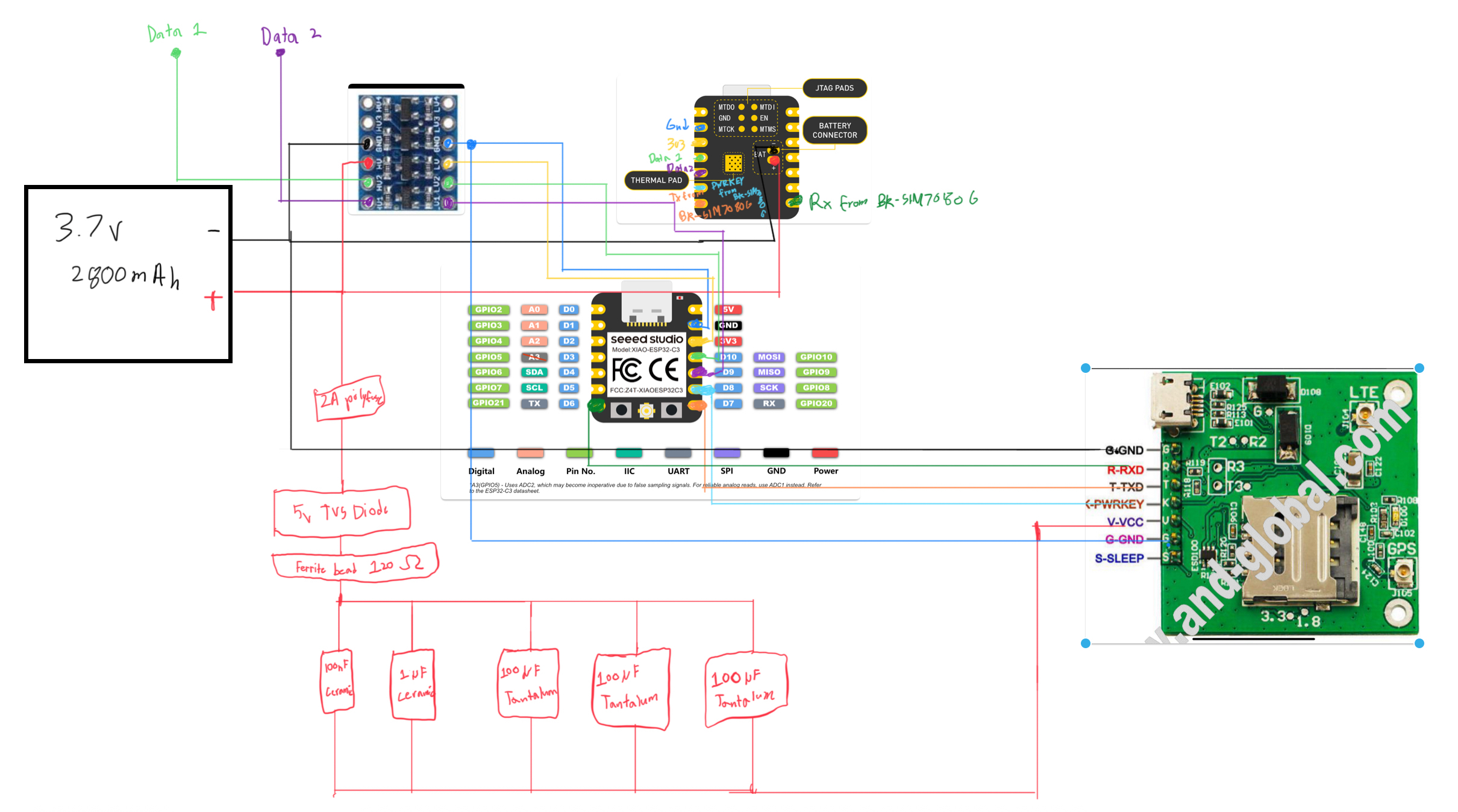
Hi, I’m trying to add cellular to my project but I am not sure if I am powering the BK board correctly. I need small smd components because space is very tight. I also don’t know what ESR/ESD to choose. Is this diagram correct or are there improvements that should be made? The battery is also connected to something else, which will be our main method to monitor battery life. Thanks.
SIM7080G module datasheet: https://www.texim-europe.com/Cmsfile/SMM-SIM7080G-Hardware-Design-V1.04-DS-200525-TE.pdf
BK-SIM7080G datasheet: https://img.yfisher.com/m0/1692268963889-bk-sim7080g-board-user-manual-v10.pdf
ESP32-C3 XIAO datasheet: https://files.seeedstudio.com/wiki/XIAO_WiFi/Resources/esp32-c3_datasheet.pdf
13 Replies
EMI is a challenge btw because my nearby electronics have an emi shield
It looks like you have VCC on the cellular module connected to a level shifter?
V-VCC? It is coming from all those capacitors
Oh, I see. It's connected to the battery which is also connected to the level shifter.
Yes
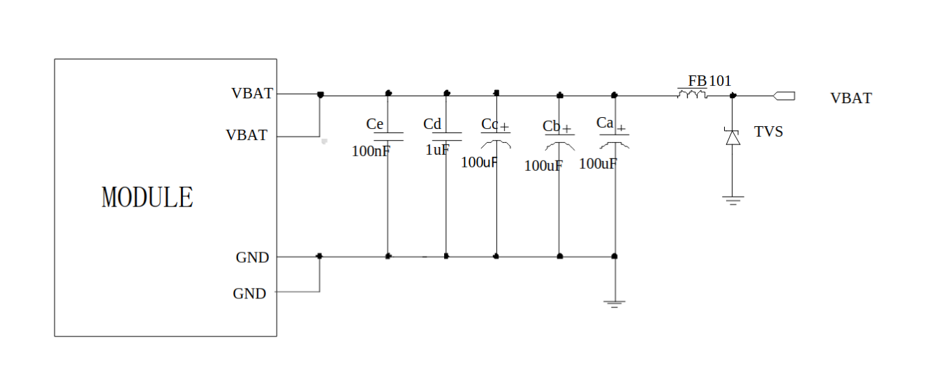
So, this is the schematic from the datasheet.
Most of these components are in parallel, other than the ferrite bead.
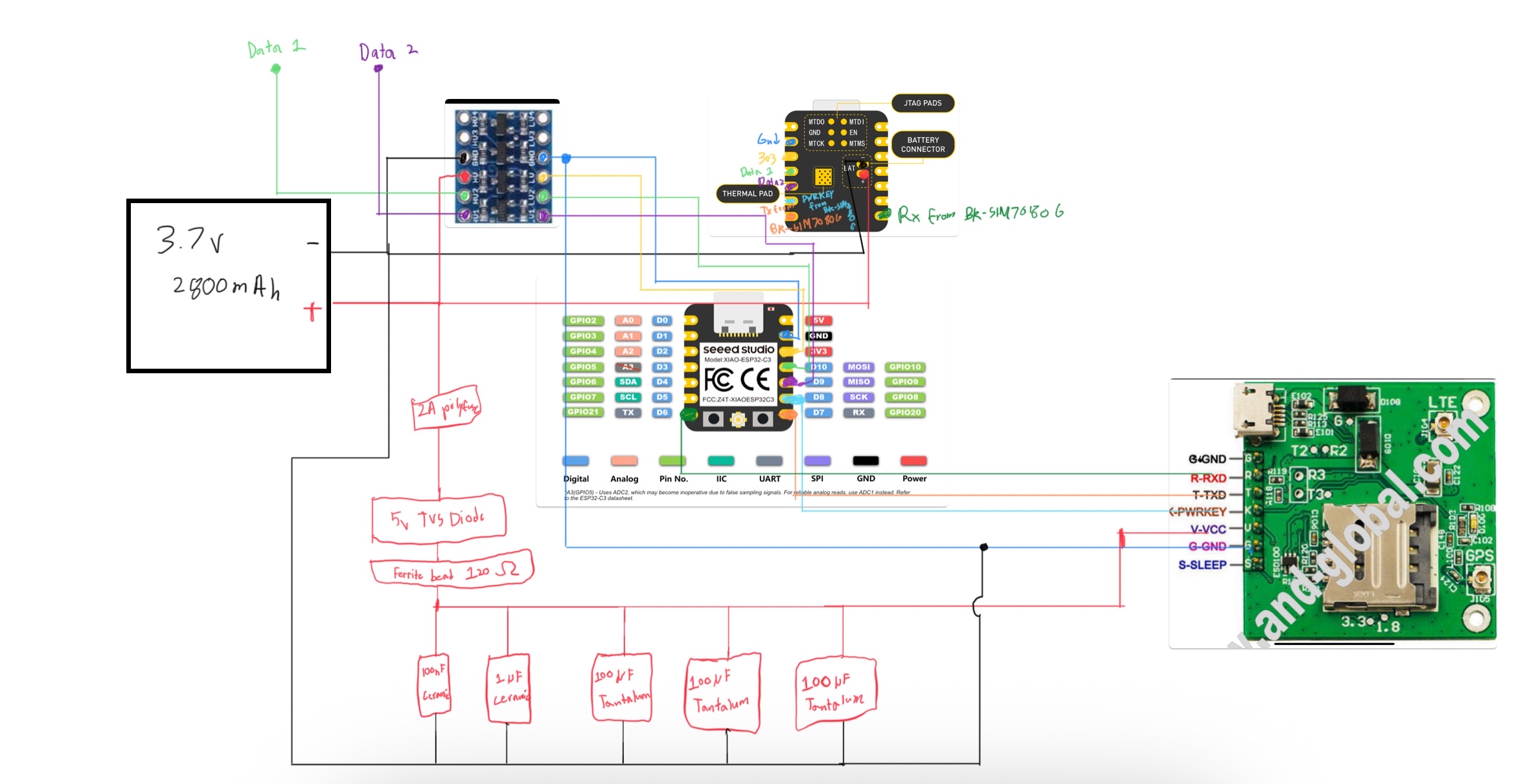
Fixed ground as well
Are you designing a PCB or just planning the connections between different breakout boards?
Either way, it might be better to use software like easyeda or kicad for the schematic.
The TVS diode should be in parallel like in the schematic from the datasheet.
Are the blue and black ground wires connected somewhere? The ESP32 and cellular module need a common ground for communication to work.
Maybe I will get a custom pcb but the idea was to originally manually solder small smds. I will look into a schematic tool. Right after the cap array the black wire meets with the blue one
@Maverick do you have any suggestions for capacitor material?
Found this schematic
Good find. I was wondering if there were already some capacitors there. It looks like there are.
I don't know about materials. I know the smaller ones for filtering noise are usually ceramic but the larger decoupling caps are often electrolytic.
Does this mean I can plug and play?
There are only two caps there, no TVS diode or ferrite bead. I would follow the recommendations in the datasheet.