Any RS485 hacker experts?
Is it possible to send two TTL devices over an RS485 to TTL module?
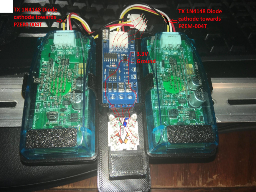
I was able to get it to work directly connected to a UART to the TTL devices with two 1N4148 Diodes on the TX lines, but then when I tried the same method over the RS485 to TTL module it wouldn't pass the data though.
I then injected the same data after the RS485 to TTL module into the devices then they spammed back to the microcontroller the data over the 485's so basically it's just not getting the signal from the micro to the devices to send the data back with both units on the other end plugged in.
(I know this is hacky and I know I could just buy a third module to get it to work)
I just wanted to know with some circuit wizardry if it was possible to make it work like with the diodes etc but the opposite way... (I tried putting diodes on the RX lines the opposite way but it didn't work)
58 Replies
@KelllTainer
Woah, but I'll take a look
Looks like you've done a ton of work here.
You would (if your desire is to have two devices transmit on the same rs485 buss in this configuration) need a multiplexor.
Your micro controller would have to tell it to switch, and you would need to know beforehand who you were switching to for what.
Not having any real part numbers or anything to work with, that's the best I can tell you. It's easy to drive one way from one device to several hundred. (255 in the case of DMX) And they can all talk back to you as well. The protocol is arranged for that.
I don't think these modules would have built in negotiation.
Or maybe I'm reading this wrong, and you are saying you have two ttl devices that want to share one pair of inputs to the rs485 converter. In which case, I would still multiplex it.
You can built a ttl multiplex circuit with discreet components. Knowing more about what you're trying to do would be helpful. The setup looks well thought out
Ah, ok. I see what it is now.
Again, multiplex, and active control of some kind. Because you'll never know who's trying to send what.
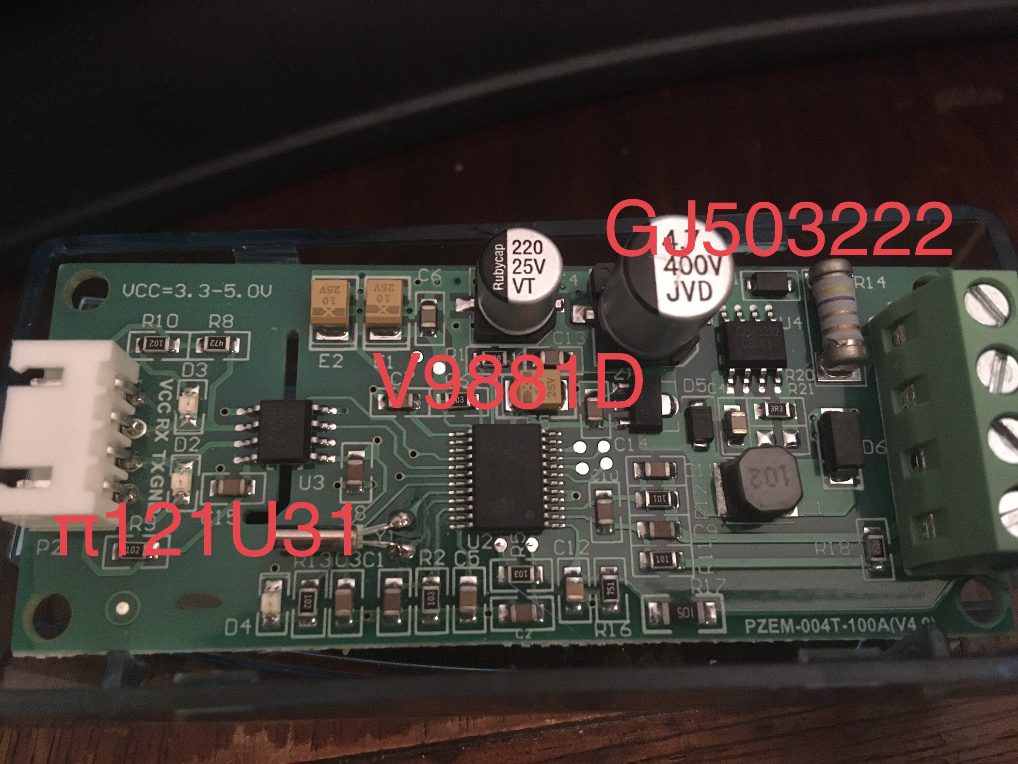
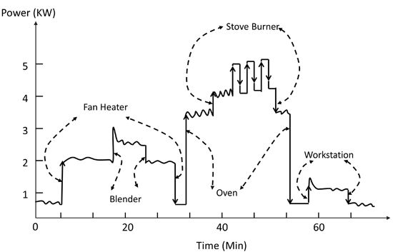
The two blue modules are TTL V9881D power monitoring chips
It's purpose is to monitor the full house power with CT Clamps for machine learning to then use non-intrusive load monitoring energy disaggregation to determine large loads. Like this is your dryer running because of this power signature or this is your oven running. Then you can make sensors for automation to then remind you turn the oven off or go grab your clothes etc.
I tested both modules connected to an ESP32 on the same UART connected like above and it was able to communicate to both of them fine back and forth with the diodes added.
The Load Centre that it will be monitoring is 15M from the server rack, which has a central ESP32 in it that monitors a lot of other house sensors and functions.
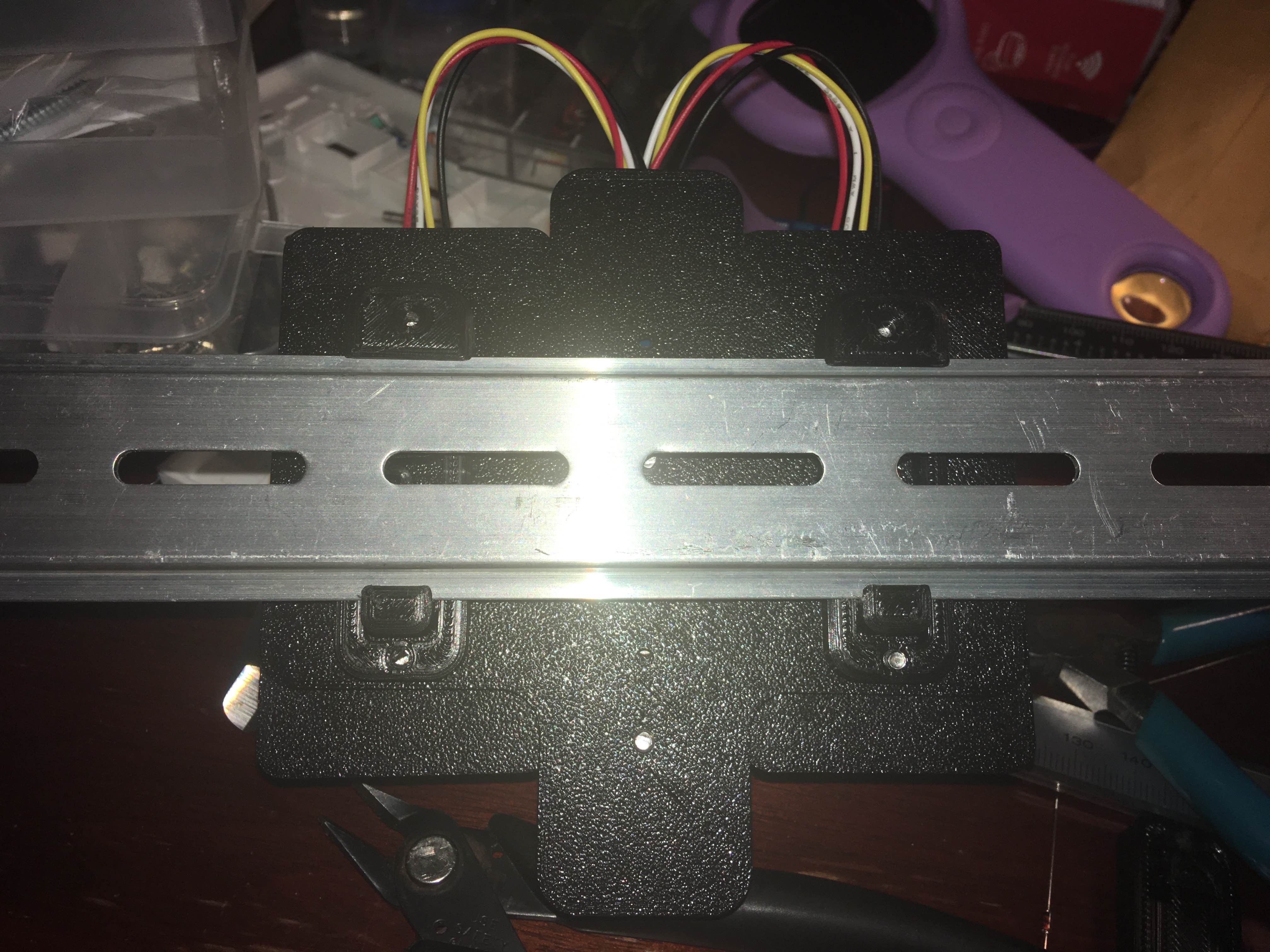
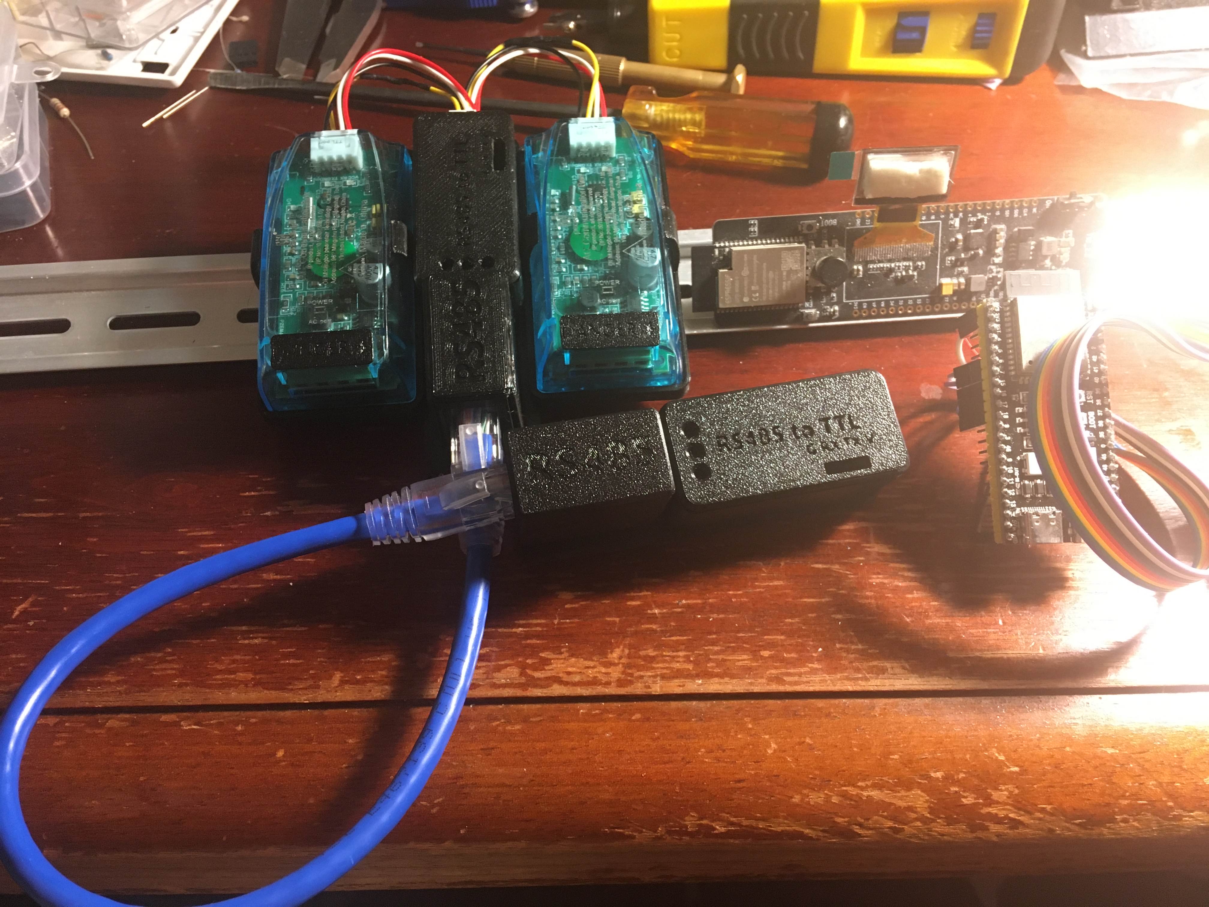
There will be an ethernet cable running between them for the RS485 connection which for now is represented by that short blue cable in the pictures
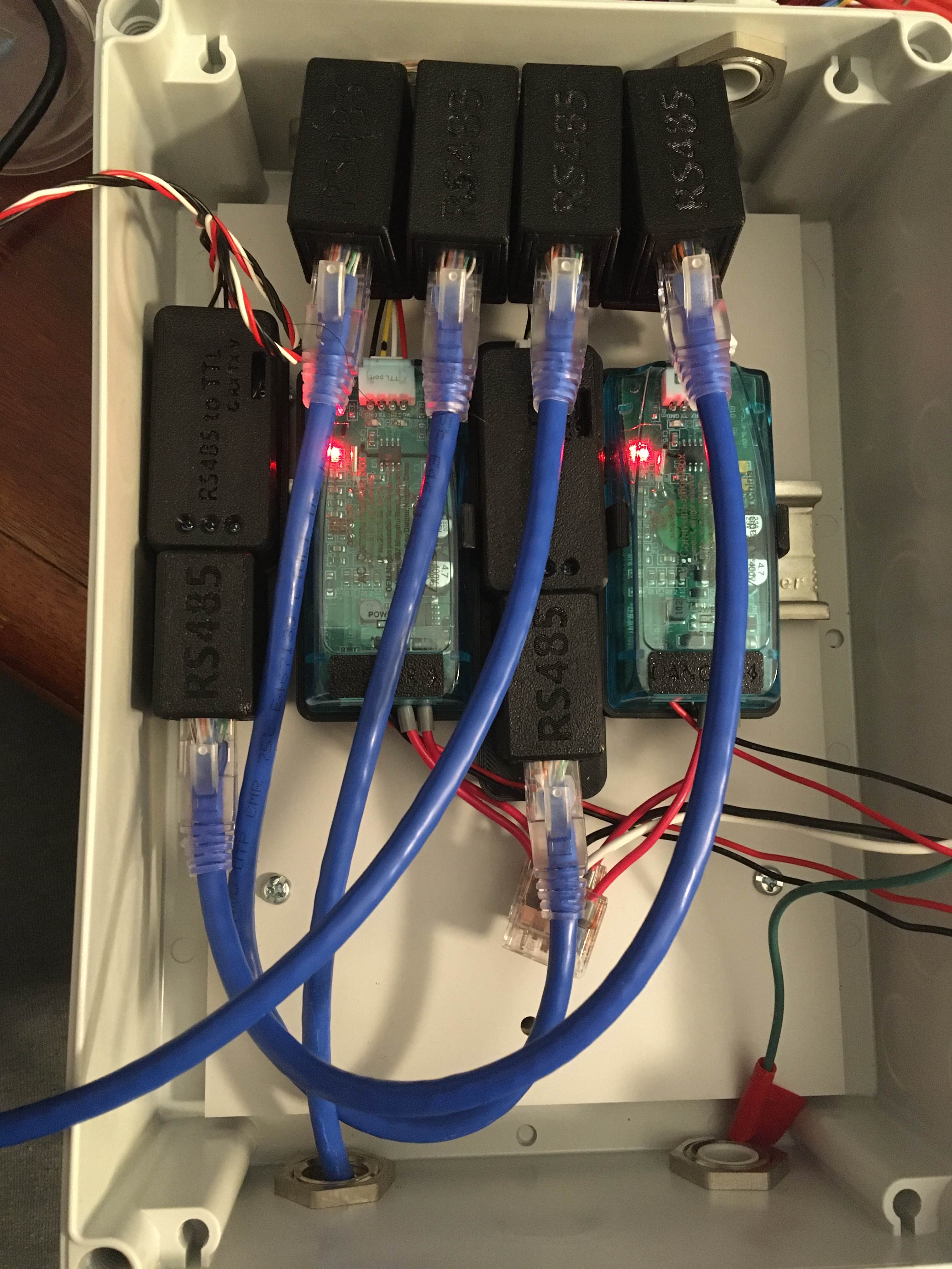
There are two RS485 to TTL modules at both sides of the run.
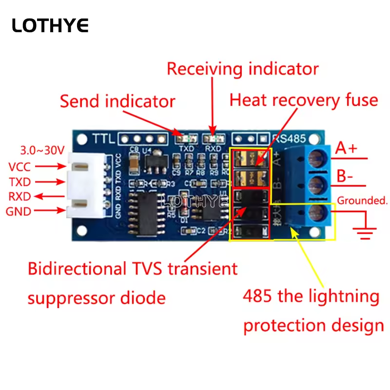
these units specifically
I then bought two of these 485 modules to go the 15m distance and thought it would just be a drop in and done 😄
The devices use modbus
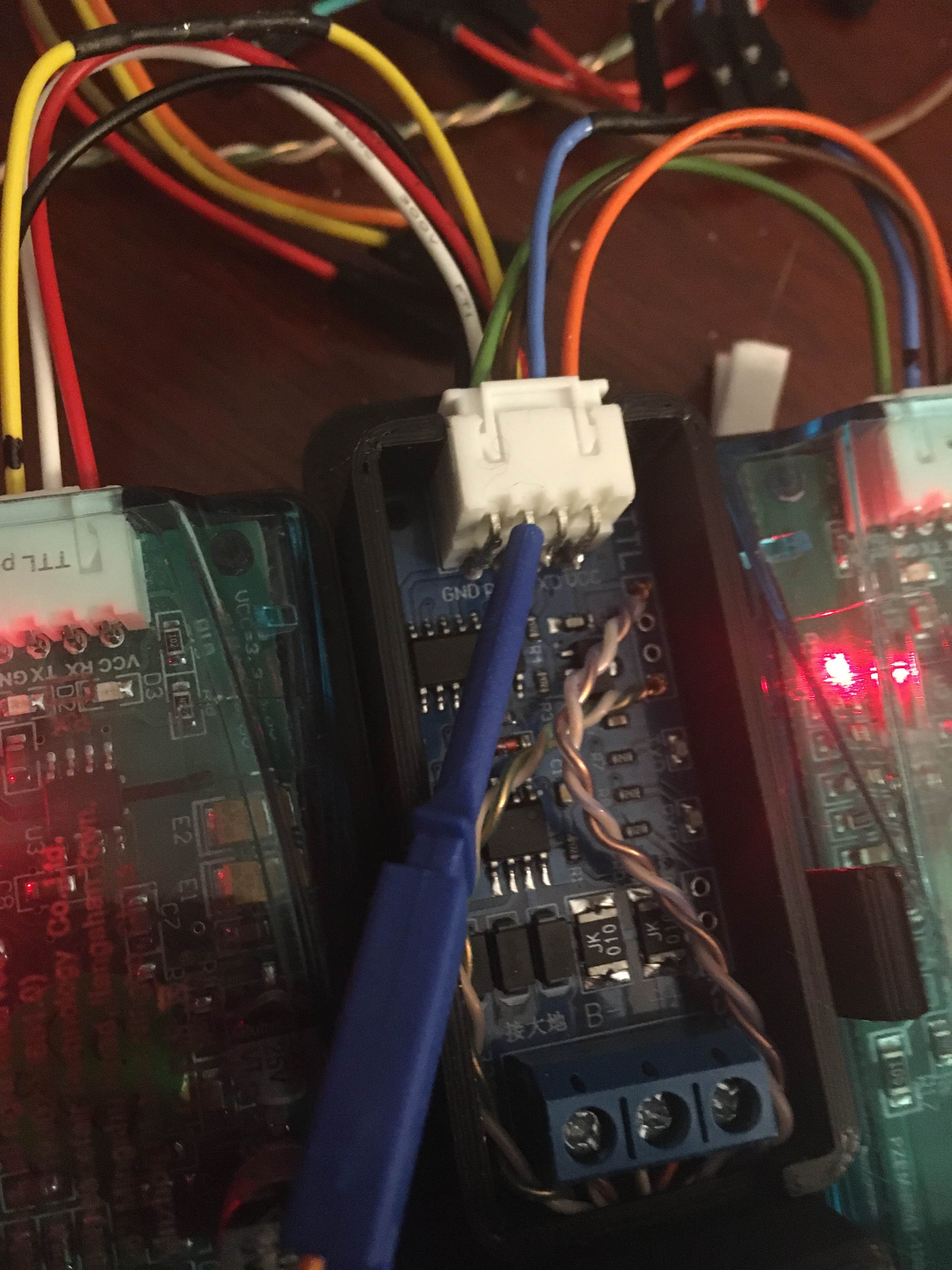
I injected a ttl signal from another uart on the same ESP32 here with this blue probe and then both devices responded properly over the RS485 link back to the other UART on the ESP32
So I thought I would just have to add a few components to load the lines properly so that it could be triggered via the RS485 path and was just missing what that was.
If I unplug one of the devices the commands succeed over the RS485 module and respond.
.
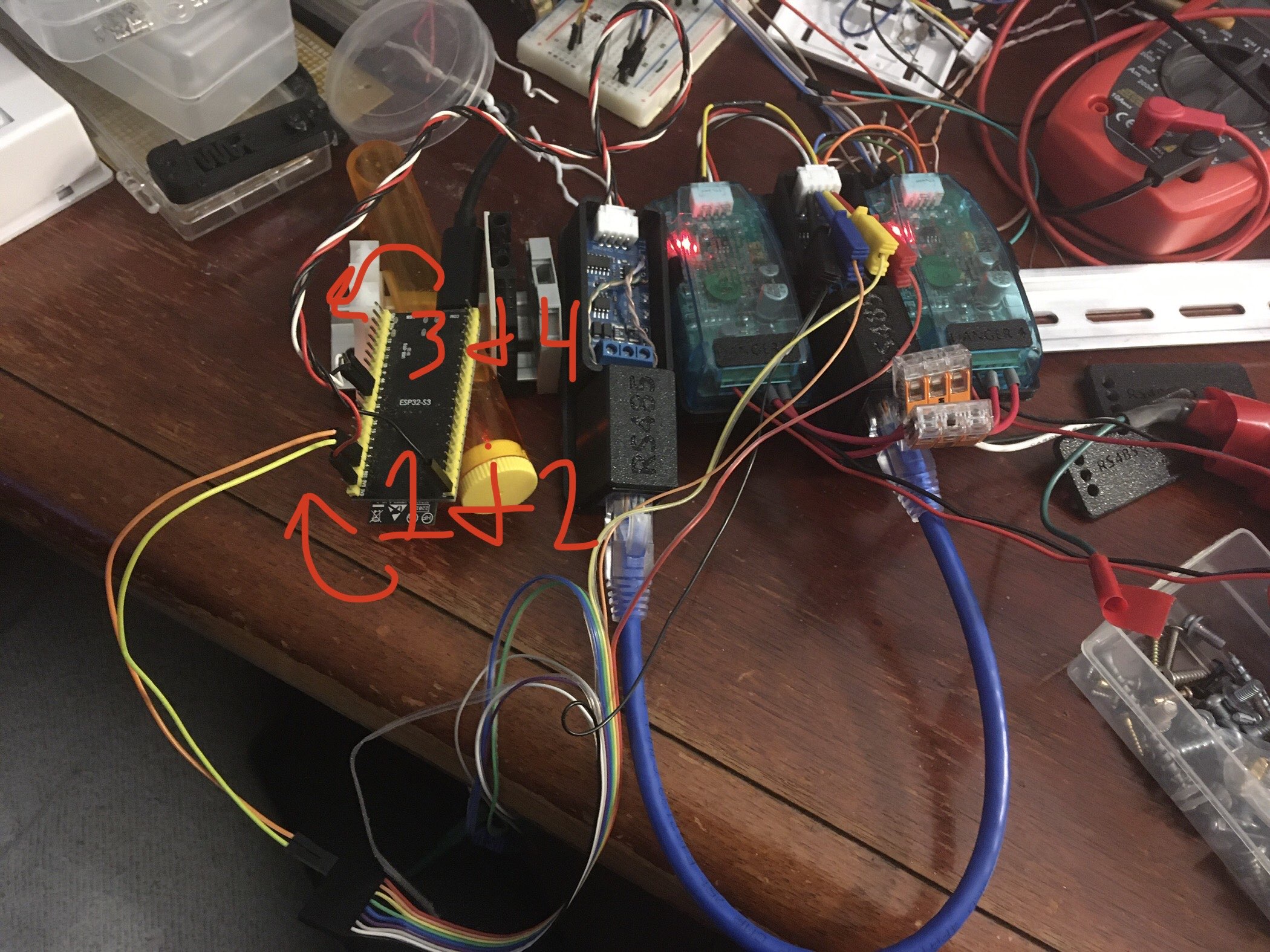
1 & 2 mean direct TTL injected with the probes to device #1 and #2
3 & 4 mean rs485 to the same devices but named them #3 and #4 for log sake.
Using two UART's on the ESP32-S3
I've set a two second delay between each device poll. I get this when the 1 & 2 probes are not connected.
Then when I inject TTL here
It will dump device 3 & 4 over the RS485 link
If I added the RX TTL probe as well, we would also see #1 & #2 responding there but I left it off for this log.
Each device you can set an address for via the modbus commands so 1 is 0x01 and the other is 0x02
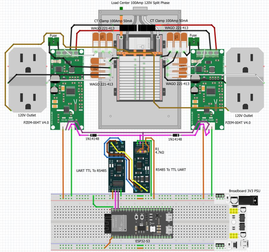
This is the full setup.
only the left module will be near the load centre and the right module will be in the server rack.
I am confused.
why not just wire them
donsky
donskytech.com
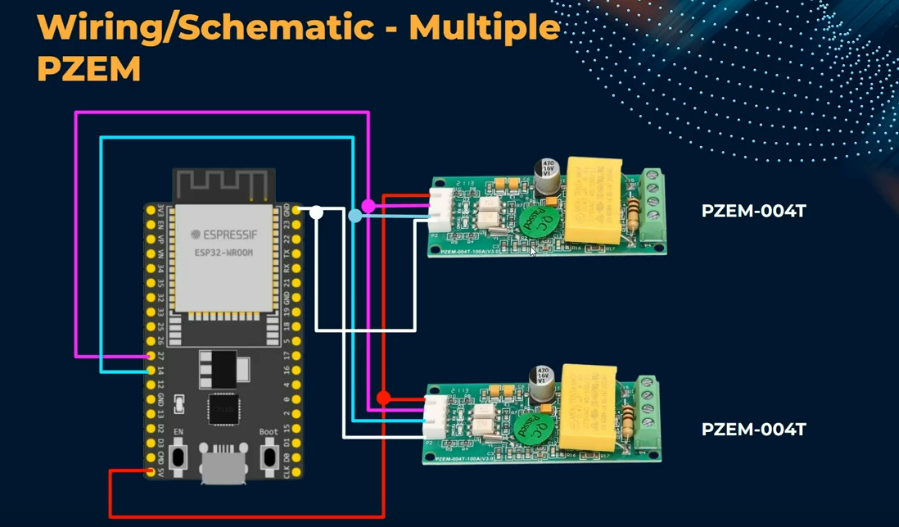
ESP32 and PZEM-004T: How to retrieve multiple PZEM-004T readings us...
This post will discuss how to configure your ESP32 to communicate with multiple PZEM-004T modules to retireve power readings from AC loads
@NonaSuomy
Yes this works. Now do that with 15metres of cable between the PZEM and the ESP32
Yeah. serial as wired into the RS485 ----> RS485 --- into the two PZEM
Yup this doesn't work.
They are designed with address numbers for multidrop serial
Correct.
I've set them to address 0x01 and 0x02 but there is electrically a limitation with RS485 where you would need 1:1 an RS485 to TTL converter module per PZEM module.
I wanted to use 1:2, RS485 to TTL converter module to Two PZEM's ie how it was working here but the esp32 replace with the 1 485 module.
Ok checking the V4 is RS485
It's TTL
PZEM-004T V4.0 Voltage Current Watt Meter Single Phase Small AC Vol...
PZEM-004T V4.0 Voltage Current Watt Meter Single Phase Small AC Voltmeter TTL Modbus Electric Energy Meters No outcaseNingbo Peizheng Electronic Technology Co., Ltd为你详细介绍PZEM-004T V4.0 Voltage Current Watt Meter Single Phase Small AC Voltmeter TTL Modbus Electric Energy Meters No outcase的内容,包括PZEM-004T V4.0 Voltage Current ...
Seems to be confusion, seen diagrams for this that show 485 hardware - But yeah - as you say - the T denotes TTL type
Not sure about the T specifically meaning that as all the way from version V1,V3,V4 they seemed to have been called 004T
How many of the rs485 units do you have ?
One thing that may be upsetting the arrangement is that the boards you have are bi directional but via some trickery.
Usually for bi directional RS485, you need 4 wires.
one set for tx and one set for rx.
Your boards use the two wires but detect the required direction.
If you have 4 boards, you could try using one set for the TX and the other set for the RX
THVD1424: Difference between RS-422 and RS-485 4-wire implementatio...
Part Number: THVD1424 Other Parts Discussed in Thread: AM26LV32 , AM26LV31 Hello,
I am trying to understand the difference between RS485 and RS422. I have read
@NonaSuomy you still working on this or what? 😕
2
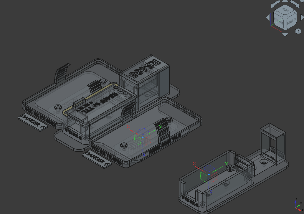
I just got defocused on the hardware portion to design a 3D printed modular RJ45 RS485 Hub as I’m not sure it’s possible with just two modules without a lot of work. If there is a method beside buying 4 modules. I’m all ears.
The devices have address set. Have you done something like this before?
Could the control signal be sent over the existing two modules or you would need an extra wire per module like a cs line on an SPI bus
The fact that these modules already have an address to know who is talking seems like there should be another method
Do I maybe just need Termination Resistors: Place 120Ω resistors at both ends of the bus to minimize signal reflections? I guess this is just for long runs
Well, the standard is to always terminate the end of a run.
The electrical reflection causes the square waves to appear tilted, and leads to all kinds of problems. If you ask Doug Fleenor from DFD (DFD.COM) always, always, always terminate.
Also, cat5 or 6 appears as 110 ohm cable. So that was an excellent choice.
I don't know the noise level of the environment, but good job!
So what is the process of hooking up multiple PZEM's through 1 rs485 link?
Others have made good suggestions. I would need to have them to experiment in my case at this point.
Hmm... The only suggestion was use 4 ttl to rs485 converters, all I have is two. Which was the requirement of the question. I might as well just buy one more to have 3 instead of 4 at that point.
You need what the PZEM or the TTL to RS485 converters?
If pzem, this is generic, any multiple ttl devices, over any single TTL to RS485 bus. So you could have 10 arduino running modbus with different addresses, attached to one TTL to RS485 converter then to another RS485 to TTL converter to a single arduino.
I wanted to know about the method you suggested as it more along the lines went with the question I asked.
You could use an ESP32 module. They have multiple UARTs.
So, RS485 -> ESP32 ... ESP32 UART1 -> PZEM1 ... ESP32 UART2 -> PZEM2.
You could also create an RS485 network where the main controller polls all of the devices but you would need an RS485 module for each PZEM. The main controller would send a request with an address. All of the devices have the receiver enabled. On the controller, DE/RE are set low after sending the request. The device in question responds after driving it's own DE/RE high, then re-enables the receiver, back to low again. The next device is polled, and so on.
It appears to have been explained. You need 4 wire, not two wire units for proper bi directional traffic to multiple devices. The circuit for bi directional 2 wire uses detection if traffic to send OR recieve.
It can't do both at the same time.
So either 2 x 2 wire both ends or a 4 wire unit
I think you guys are talking about RS422 using differential wires. I’m asking about this method said here about using a multiplexer. What would be the method to do this over RS485
Why? Im asking g what is the limiting factor to two wires.
I'm unfortunately not in a place to help with this due to a lack of time for the next several days. Sorry.
They require bi directional all the time. The 2 wire swaps.
https://discord.com/channels/420594746990526466/1403291818296086568/1404249794016186430
No worries, whenever you have a moment, please lay down the know how. I will randomly check back in.
Seems a waste of time to explain Bi-directional half-duplex vs Bi-directional full-duplex
You need Bi-directional full-duplex to have two devices or more on the other end.
The first comment in that post explains how you would handle multiple devices with half duplex RS-485.
I think the user here wants to multiplex on the UART side of the RS485 transceiver though.
They have tested the setup wired directly with no units between. - it works
They have tested the units with the 485 units with one device on the far end - it works
when they add the second device far end - it stops working
The devices use the Modbus-RTU protocol. It should work if done correctly. Here is the datasheet. https://innovatorsguru.com/wp-content/uploads/2019/06/PZEM-004T-V3.0-Datasheet-User-Manual.pdf
I am confused. The modules are already 485. So you should only require one 485 -> TTL on the esp end ?
Too much coffee??
That is correct, then the two pzem devices are connected on the other end with termination resistors for the ESP side and whichever pzem devices is farthest from the ESP.
Oh, there are two types. TTL or 485
Ah, maybe they have the TTL version. That would explain wanting to multiplex on the TTL side of the RS845 transceiver.
It seems they have the ttl
There isnt a good way to mux TTL this way without a ton of extra bidirectional work
which, i believe would be a lot of extra work that would take away from the work on the suggestions of "bi directional rs485"
My thought was something like an ESP32 which receives the request with an address and then uses UART0 or UART1 based on the address to get the data from either pzem device and send it back over RS485. Would need 3 UARTs in total. One for each pzem and one for the RS485 transceiver.
Seems to be a message lost in the wind
https://discord.com/channels/420594746990526466/1403291818296086568/1410412931882942536
The half duplex will only work with one device at the other end.
One month later....
(the wind blew this thread away)