Panel Solar on the payload for Atmosferic Baloon
Hello everyone,
I am Federico Dalla Vecchia, maker and engineer.
The final part of my project is to integrate a solar panel with Arduino.
The goal is to measure solar radiation intensity during the day. More precisely, I want to record the raw data as voltage from the solar panel, which will be mounted on top of the payload of a high-altitude balloon. The payload will fly from the ground up to about 30 km altitude in 2–3 hours.
I would like your advice on how to design the circuit.
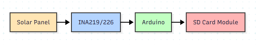
At first I thought about a simple voltage divider with precision resistors, then I considered using an easy module with a shunt, like the INA219 or INA226.
I am also unsure which solar panel to use. If you have any suggestions or experience with these instruments, I would be very happy to learn from you. Thanks new Community 🙂
10 Replies
Here are my recommendations:
Circuit Design Considerations
For Solar Radiation Measurement:
Since you want to measure solar radiation intensity (not power generation), I recommend:
Use the solar panel in "short-circuit current" mode - Solar panel short-circuit current (Isc) is directly proportional to irradiance, making it ideal for radiation measurement.
INA219/226 is a good choice because:
It can measure both voltage and current simultaneously
Has built-in ADC with good resolution (12-bit for INA219, 16-bit for INA226)
I2C interface works well with Arduino
Can handle the low currents from small solar panels
Solar Panel Selection
For radiation measurement at high altitude, consider:
Small monocrystalline panel (5-10W range)
More stable temperature coefficient
Better spectral response
Example: 6V, 1W panel (approx 170mA Isc)
Important specifications:
Known Isc at STC (Standard Test Conditions)
Low temperature coefficient
Wide operating temperature range (-40°C to +85°C)
Recommended Circuit
Ehi 🙂 , thank y so much for the answer. I have pondered about the sensor. I have a mini panel solar like this: RUNCCI-YUN 4pcs 5V 30mA 53×30mm Mini Solar Panels (from Amazon). This measure a little current and to be honest, i have measured 0 current mA with my Multimeter, but only voltage... i dont know why.... So the INA219/226 is not necessary to measure this low current... maybe i could use just a resistence... What do you think about?
@sven 🙂
Hey Federico!
I see what's going on - those 30mA panels are really tiny.
The reason you're not seeing any current on your multimeter is probably your multimeter has internal resistance that's dropping the voltage too much
Circuit:
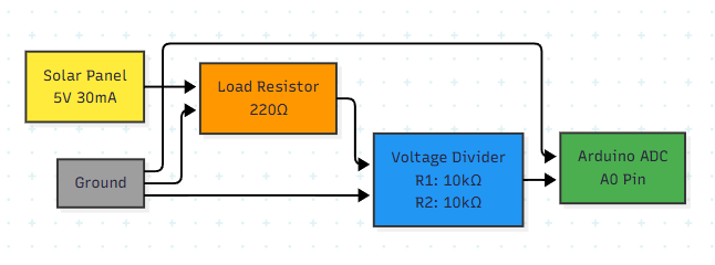
Yesssss
In this mode we can measure the current fixed by load Resistor. This currents varies thanks to the variation of the voltage form the panel solar... then the voltage is controlled by the Volt. DIv. for Arduino PIN where we will program the reading of the currents... But i have these doubts:
1 ) Can we read all I-V curve?
2) If I use a variable load (like a potentiometer), what will I observe?
@sven
Thanks the fast answer 🙂
Overall, i have imagined one thing as this. 😉
light level is directly proportional to output current? I’m assuming you intend to get references of know light sources before sending it up in a ballon?
If the voltage is low at 1MEG you might need a amplifier to bring it up to a signal voltage with acceptable bandwidth where a change in light causes a noticeable change in voltage. Then calibrate it’s reading against a know light source as a reference. This is assuming output current is linearly proportional to light levels.
Yeass, i need to calibrate the measure systems with a reference, light reference. Perhaps we need a amplifier, but i want to build the systems without. Meanwhile i thank y for the answer.
@yourboi8500
Get various value resistors 10k, 100k, 1Meg ect and measure the output with a multimeter at various light levels. If the multimeters 1Meg resistance drops the voltage too low to measure significant voltage you are going to need an amplifier.

You want a bandwidth somewhere around 0-5V for the Arduino to measure with analog read. The easiest hardware, if you are building hardware and not buying modules. Would be an amplifier.
If chatgpt is right and analog read can measure in 4.88mv increments that gives you 204 increments for a single volt. The engineering will then turn into a game of stability. You will get to that problem if you get there.