Total newbie wanting to design a structure pack
So, I've followed the docs up to the counter section as I don't really think anything beyond the counter is applicable to what I'm interested in doing. My main interest is creating a pack of building blocks similar to what is offered in Structural Solutions > SS Concrete.
I've never done any kind of modding before, never used UE5 or Blender, but I have everything installed.
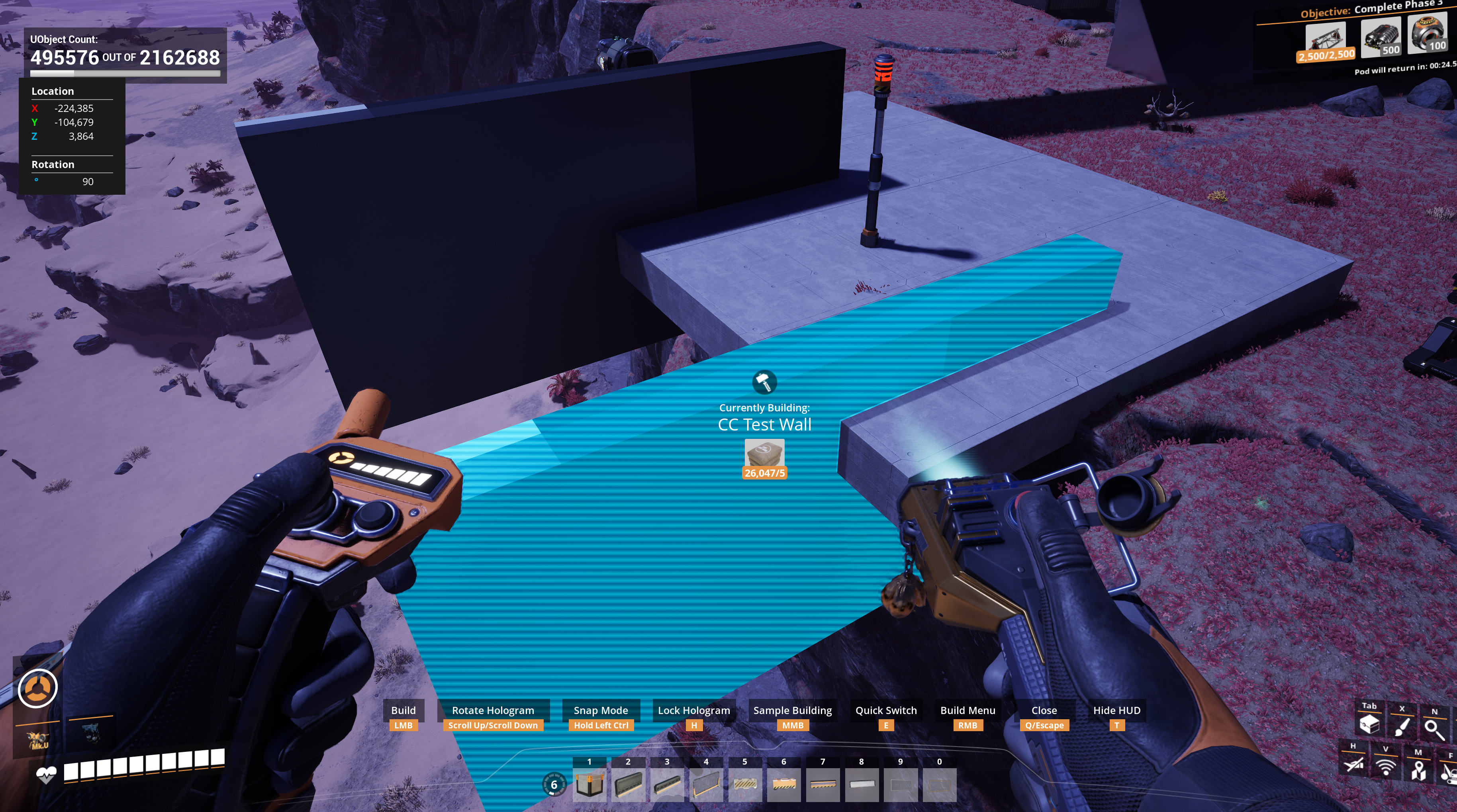
So, I've spent the last 5 hours or so trying to implement a simple wall, no special textures or anything, just an accurately sized, 8mx4m wall.
I have atleast managed to create a wall buildable that can be placed in game, but the dimensions are way out. Every time I try finding a solution, I feel like I just fall in to a rabbit hole and overwhelm myself.
I've got tonnes of questions and problems that I don't know where to start with, but i'll go with the one that's right in front of me first....
How exactly are shapes measured and placed in the view port/details pane, to reflect accurate size and placement in the game world? How much of this work is done in Blender versus UE5? Is it imperative that my shape in Blender has the correct size/ratio? (8.0, 4.0 and 0.5 being the dimensions of an 8x4m wall) or can I can make any cuboid shape in Blender and then force the correct dimensions in UE5?

184 Replies
Also, I don't understand why there are 2 objects here....

https://github.com/DavidHGillen/Satisfactory_ModelingTools/blob/master/SF_FoundationTemplates.blend
https://github.com/DavidHGillen/Satisfactory-AB_XMASBooster
My open source tool/mod here are probably good for you to look at.
The blueprint for the item natively contains a reference to the mesh, a mesh that might not be correct because we can't put the meshes in the project
thank you for these.
So i've opened the foundation templates. If I were to export one of those shapes to UE5 and make a shape directly with them, they would be the right size with no tweaking needed?
I still plan on making my own shapes ofcourse, this just answers the question that the entirety of the perfect shape and size/dimensions is managed in Blender
with regards to the XMAS Booster, i'm not sure what to do with it to help me figure this out
the templates are there to help you build meshes that face the right way and be the right size if you replace the mesh in the existing pieces. So if you were to simply copy all the items and swap out their meshes with the templated versions it'd be good.
The XMAS booster is a mod that has a major feature being an alternate style for deocr, of gingerbread.
this includes all my source files as well as the plugin files needed to load the mod in the modding environment
this folder right here contains all the stuff needed to load the mod in unreal. the way I do it is to make a symlink from
sml/mods/
to that folder, but you can just copy everything out of it instead
Thanks man, i'll have a look through it later. My brain is fried right now
Am I right in thinking that there's no reason to be adding materials to shapes in Blender when the Shapes are going to be used as building pieces?
It seems to me like I need to create/import a material in to UE5 that will be applied to every single block... Since I want all the shapes to use an identical material/texture.... No unique patterns in specific places.... Just a natural concrete/plaster material across all the buildables.
So I can just make plain, untextured blocks in blender, and then import a material in UE5?
Yes. You do need to UV it properly in blender. But you should use unreal materials. And if you can reuse existing materials with new textures.
I don't really know much about UV.... Would the quick option "Smart UV Project" suffice?
So, make a shape of accurate dimensions,
Do Smart UV Project,
Import mesh to UE5,
Configure all the bits to make it a functioning buildable ingame,
And.... Assign a material...
Is that essentially what I need to do?
Learn what UVs are and how to do it anywhere the internet will teach you. They are an essential part of making models that show any hint of texture beyond a flat color.
thanks, yea I just finished reading about them
managed to get a shape with properly distributed materials on all faces
@D4rk
Hi D4rk, I've been encouraged to seek your help on a problem I'm having in creating a material to be used in structures.
My main inspiration for making this structures pack has actually been your SS Concrete structures.
There's just 2 things I can't seem to replicate in the material node graph. Muppet has been trying to help me through but ultimately I think your input is needed.
Basically, your SS Concrete can do 2 things which I would like to replicate:
1 - When Shiny/Metallic finishes are applied to an object in game, the entire textire of the object changes, and all the patterns and roughness disappear.
2 - When your SS Concrete shapes overlap with each other, the textures merge seamlessly and appear as though they belong to the same object.

This is what I have at the moment

and these are my walls (on the bottom) compared with your walls (on top)
Left is a shiny finish, right is a normal paint.
and for further clarification, this what I mean by texture merging.


When your SS Concrete shapes overlap with each other, the textures merge seamlessly and appear as though they belong to the same objectLook into tri-planar projection
Would that be better than using WorldAllignedTexture?
This is worldallignedtexture method (on a shape that was subjected to UV Unwrap)

you can still see a faint line

this is Worldallignedtexture (on a shape with no UV unwrap)
So, I think that's 1 problem solved?
use Worldallignedtexture, and don't unwrap the shapes before exporting from Blender
basically the same thing as what I mentioned
oh, sorry, I tried watching some videos on tri-planar projection and it was going over my head a bit :/
To get rid of the normals when a finish is applied you lerp between the texture normals and the vertex normal using the MF_GetMetallic as an alpha. It's the same thing you did for the metallic and roughness but in this case you need to also transform the world space vertex normals to tangent space (materials expect normals to be in tangent space by default, but you can change that setting in the main material properties)

And yes, as Beaver said, my concrete material uses tri-planer mapping, Ben Cloward has some excellent tutorials on youtube for this.
Ben Cloward
YouTube
Using Position Data - Shader Graph Basics - Episode 26
In this shader tutorial, I explain the different types of position data that are available to bring in to your shader (object position, vertex position, pixel position) and then we take a look at 3 examples of how to use position data. We use position data to apply a dark-to-light gradient to our model, to create a location-specific mask for our...
Also, even though tri-planer does not require you to uv your meshes, you will still need to uv the foundations for patterns. A top down 0-1 projection usually works fine.
Great, thank you for confirming all of that! I'll have another go at understanding triplanar mapping

Okay, that's single, and triple texture sampling
I'm curious, did you get away with single sampling (no texture merging) and hard edges on your material?
I'm looking at it in the materials window and on a basic 8x4m wall in UE5 and it feels like the single, light option with hard edges/seams, is entirely unnoticeable
but considering your experience in this, maybe you know something I don't
I'm using your SS Concrete blocks in my save by the tens of thousands, and my FPS is still solid. No performance issues... And considering your shapes are essentially my benchmark in trying to make my own structures, I wouldn't want to make a material that can't perform aswell as your has in my own save.
actually, it dawns on me that i've only done this on the base colour so far and everything will change when I apply this to all the textures

okay.... assuming that the MF's I made are correct, I think this should be finished

Ooooookay... So i'm basically at the same stage as SS Concrete as far as my material is concerned

this is the updated material node graph
Now, what i've been trying to tweak (unsuccesfully) for the last 30 minutes, is the metallicity
I'd like the metal to look a bit more like other metallic finish to look a bit more like other metallic finishes
less "fuzzy"
I figured that the fuzzy effect is coming from roughness, but any tweaks I tried making to the roughness didn't get the result I was looking for
I assumed I would need to create a lerp in to roughness, that included GetMetallic in the alpha, but that just made the whole material very matte-like

this is the sort of metallic finish i'd like to reach
How did you get such smooth looking edges to work with tri-planar projection?

soon as I apply shade smoothing, i get this problem
there's some smoothing going on here, and yet your shapes don't flicker when they overlap like mine do.

I've been playing with this for hours and googling non-stop but im not closer to finding a solution
Are you using weighted normals on your shapes?
My research led me to start looking normals last night but it was bedtime by that point.
Thanks, I'll see what I can do with that

I spent the better half of yesterday searching Google, asking AI and watching videos about this problem
and not once did anywhere mentioned weighted normals 🙃
But, that worked, thanks again.
no worries, it comes form knowing how the tech works to know what problem you were probably having

Well, all the ground work is essentially finished.
Now it's time to start on the hundreds of individual shapes
Thanks again for everyone's help on getting me this far
I really like the SS Concrete structures and my whole map is built out of them.... But I want more shapes 😋
So that's basically the goal.... Something with all the benefits of SS Concrete, but with more shapes
Smaller versions of everything
For extra detail
Looks good, glad you got it working!
The vanilla holos aren't really designed for very small or very big parts. The main reason there aren't many of these in SS is because they are annoying to snap. If you want parts that are <1m on any dimension you will probably need a custom holo.
Ah, that will explain why my 2m wide foundation doesn't like snapping on top, and to the edge of another foundation
As soon as I move from the centre towards the edge it starts snapping to the side
But.... If I remember rightly, making holos requires writing code 😕

These pieces seem okay, but the smaller foundations are funny
I'll be honest though... I'd rather tolerate the funny snapping than have to learn how to write holo code
Maybe someone out there wants to work with me on that part? 😅
I've been having a more significant problem with the snapping of my 8x4x4 foundation actually... I assume the problem is with the lightweight copy of the shape.
When I place the shape, it initially had the correct alignment
But when snapping anything from the first shape that was just placed, the second shape becomes rotated 90 degrees
The lightweight has the same scale value as the main mesh and no rotation transforms
So I'm not sure what the problem is
I'm just getting out of bed and taking the dog for a walk, but I'll take some screenshots when I get back
So this is the static mesh I'm using for the basic foundations. It's 8x8x4.

as an 8x8x4 buildable, it's working fine
The problems are with this Buildable (8x4x4) and with the next size down (8x2x4)


I realise here, I've got width value set to 400, instead of the depth value. When I had the other way around, the snapping was completely wrong.
compressing a video to show the problem
The white blocks are mine, the grey blocks are SS Concrete
As you can see, SS Concrete retains orientation of blocks placed on top and to the side
but my blocks are turning them 90 degrees
If i change the width and depth values around, like I assumed it should have been at first... it does nothing to change the problem and only makes things worse


So, it seems width matches with Y and Depth matches to X
All I can think to do, is transform the lightweight to show different faces after placement, but that seems like a janky solution to me

surely the lightweight should be identical to the main mesh
okay.... so, I think I found the answer, but maybe someone can explain the reason to me
Instead of transforming the shape on Y, it has to be transformed on X
So I had problems when XYX = 8x8x4 was transformed in to XYZ = 8x4x4
But now the shapes is transformed on Y it's fine (XYZ = 4x8x4)
It doesn't make any sense why it would react differently because the shrinking happened on a different axis :/

I'm currently analysing the MM_BakedStencil and comparing it with your own material

you've made a number of changes to it and I suspect I don't need alot of them...
No. I'm using something far more complicated than triplanar worldspace UVs
Wobble for example.. I suspect your trying to wobble the pattern over your foundation
and you've injected a permanent texture
And on top of that there's new features like making the markings look like icing, sparkling sugar in the bread. Etc
I assumed I just needed this piece of the MM_BakedStencil?

1 output
Looks about right at a glance. Just test thoroughly
This doesn't come with the normal texture included in BakedStencil, nor does it have the albedo textures
So I would just lerp that one output with my base color?
these are all the bits im ignoring

Depending upon what you want it to look like you can choose to mix in some or any of that. Just follow the wires and think 🙂
so after trying lots various combinations, and doing a bit more reading on exactly how lerps work and what the function of the alpha is...


I conluded that I should take the output from Stencil and Top Mask, and use that as my Alpha
and then put my primary colour in to A and secondary color in to B
it doesn't work ofcourse, and i'm not sure why
I'm thinking that the Stencil/Top Mask goes in to the Alpha, because the Alpha is used to determine the Mask that the 2 colours should use?

but it just blanks my whole material
So a lerp node blends A and B according to Alpha
If Alpha is 0, you get A
If Alpha is 1, you get B
If it's somewhere in between, you get a blend
For your shader to be reverting to world grid like that means something somewhere is very broken. a simple lerp wouldn't do it
It's probably failing to compile
The Stats window shows compilation errors
Its probably something simple like you've plugged a float4 into an input that only accepts float3, or something like that.
i gave up on it. After trying to get the stencil to plugin to my own material (unsuccessfully), I made a new material consisting of only the stencil graph and plug everything directly in to the main material node... played around with that for maybe 2 hours, and couldn't even get that to show me a stencil on a foundation.... so, if I can't get the graph on it's lonesome to work, I think i've no chance of getting it to work in my own material.
If you give up it will never work 🙃
The whole materials system is just too much for me. I don't want to take on that sort of challenge. Figuring out how to wire up that stencil graph, means studying the detailed workings of all the various nodes
the explainations of the nodes (CTRL+ALT) don't even make sense to me
The stencil logic is really just a fancy mask, and it should probably be wrapped up into a function
when the mods finished, i'll likely make it open source
so someone can re-upload it with any material they like
and a working stencil graph if they know how to do it
and, there'll be a few hundred meshes that people can use for their own mods
The default value for the stencil parameter is 0, that means no stencil
Did you try changing that?
yea i searched this discord and read more than half the messages containing the words "stencil" "pattern" or "material"
and i found the message where someone mentions that problem
I didn't say Discord
no, i know, I just found the problem you're referring to, yesterday, while I was searching discord for any messages related to my problem
the texcoords show 0 and should show 1, right?
This is the pattern ID that defaults to 0

That's one of the nodes on the left of the material
oh... so it's not the 0 value in texcoords
No, that's the UV channel to use and 0 should be fine
If the stencil is placed in the wrong place then check the UV mappings
I kept checking all the faces on my foundation, but it never showed on any of them
Also this StencilAtlas texture sampler needs to be set to "Virtual Linear Color", otherwise trying to use patterns will make it error out

Again. If you use
MF_PaternID
without any changes, its value defaults to zero so no stencil is shown
And that texture is virtual, so it doesn't get dumped currently
Also, this is an old error in the project. Vanilla foundations use UV channel 1 for stencils, not 0.

Oh, right, I remember now (UV channel 0 is doing some optimisations to quarter the size of textures)
And FModel can extract the stencil texture

Is it necessary to get the original stencil texture?
if you want to test it properly in the editor, then yes
Oh, I've been restarting the game over and over to test it
the "fake" file currently in my graph... will that get pulled to the game and interfere with the real graph taking it's place?
Which fake file?
Well, I'm guessing this file doesn't contain the real stencil data if you're suggesting i should extract the original

The idea of extracting the original is so that you can test stuff in the editor
I know you can display stencils in the editor if you have all textures
alright cool, well thanks for the extra info. I'll have another go at it and see what happens.
One more thing though, I'm not sure what part of the MF_PaternID is broken/wrong
Unless, you're saying, I need to change it from 0 to 1 or higher to see any results in the editor?
You somehow need to change the value to see any patterns
The simplest thing to do in the editor, especially if you have your own material, is to use a hardcoded constant for testing
in game, the number would change based on the user applying patterns, but in the editor I need to change value manually.... right?
Also remember that the
MF_PaternID
MF has a static switch parameter that you need to enable
Yesso the get_paternID works... just not in the editor, without manually adjusting it
like changing the get_colour value so your ffoundations aren't always black
Oh, it totally works in the editor, if you're willing to make a mesh with per instance data floats and make something to change them at runtime
0 is the only correct value unless you specifically authored a mesh with multiple UVs for an explicit preference
I'm trying to find an old video of mine but can't seem to find it
alright, well i've changed the stencil texture to Virtual Linear Colour, set Texcoords 1, and i've pasted the MF_PaternID directly to the graph so i can change it easily.
Next i'll extract the stencil file

I don't understand the purpose of these textures
Am I supposed to replace with my own textures or are they important to the stencil function?
replace them with your own textures
There's a principle that says if it's supposed to be changed, make it look as ugly as possible, even better if that helps you debug problems.
so weird ugly debug textures you never want the user to see often show up in materials. because material instances with valid textures should be used instead
Yeah, these are changed in MIs
At some point I made this happen


You can jsut drag a static mesh into the editor world and set data on it directly
I didn't know you could do that back then
This was back in Update 8 times
are there are settings in the detail pane that need to be enabled?
which settings?

on the left
All that looks correct.
So I've got the patternID set to 1, and the texcoords set to 1... I tried 0 aswell


and i'm linking the entire graph straight in
but with my own textures
all i get is a white cube
this is my foundation and it's UV


I would have thought that changing the numbers in the PatternID section would have changed the pattern in the Custom node?
but it doesn't
The bool on BUseCustomPrimitiveData is set to true, so its not using whatever number you assigned to PatternID

both of those numbers are synchronised
Unfortunaly setting a value there wont work in the editor, once a scalar parameter has "Use Custom Primitive Data" checked, it wont output anything other than 0 unless it receives data from the mesh component.
Create a different scalar to plug in there for the test, bypassing everything before the static switch
ooookay, finally something has appeared

it's scaled much too big though, alot like my texture
anyway, I guess i can work on injecting this in to my own material now
Try using this material with a default cube
I think the UV mapping covers the entire top face
I'm trying it with Angry's Gingerbread blocks and it looks a bit better

the scale is correct on the ginger blocks
but that secondary pattern is wrong
What secondary pattern?
the truck in the middle
I don't see any truck in the middle
I don't understand

I see two lines
What were you expecting to see?
you don't see all the black markings between the lines?
i'm pretty sure that's a factory cart path
and the middle section should be white
Ah, now that you say so, I see something
😂
im gonna load up the game and see what happens
or not... i'm pretty sure my mod is crashing my game because of the error I posted in the fitcsit labs discord
Yeah there's some ghosting from the other coloured layers that I've been meaning to look at it my image. I had to rip it because it was the only way to feather the edge so I could get a nice gradient for the normals. but there's probably better ways to get it done
Hmmm

🎉

Okay, now everything else is taken care of... I can finally look at this
I tried increasing the stencil opacity and it does help, but it doesn't fix the extra markings which shouldn't be there
If i set the stencil opacity to 100, i get this

Okay so it has something to do with these Min Max values

It's very close.... but there's alot of little chunks sticking in and out along the line

That's best I can get out of it

Does the same appear in-game when using the original texture?
yea
Comparing it to SS Concrete, those patterns have nice straight lines
and Gingerbread foundations show the same problem
so I think it's the material rather than the mesh
Could be
Would be nice if you could show your material so that D4rk can see if there's anything wrong

The blurry edges are caused by the texture mipping out. I'm not sure how vanilla solves this issue, but my method is to turn off mips. Select the stencil texutre sampler and change the
MipValueMode
to MipLevel (Absolute, 0 is full resolution)
, then plug 0 into the Level
input on the sampler.
oh, awesome, thank you!
I'm curious D4rk, Your material is stretched over quite a distance, and yet the quality is still quite high
Are you using 4 or 8k textures?
takes about 3 8x8 walls see a repetition of pattern with your material
I have a 4k material stretched over about 2 8x8 walls and it's starting a tiny bit less detailed than yours does over a wider distance
My texture set is 2k, and I have a tri-planar world size of 1301, and a Lod size of 6947
In one of Ben Clowards videos, he talks about using prime numbers for tiling sizes
I have the scale set to 0.1

Is that to avoid clearly repetitive patterns?
Yes
but i notice when i use the built in "WorldAlignedTexture" node, it wants 1000+ to match my 0.1 on the node I made from Bens video
I only use one texture that is channel packed.
R= Normal X
G=Normal Y
B=BC texture
A= Roughness
The normal z is derrived
Its sampled once for the the normal tiling, the sampled again at a different tiling and blended by camera distance for an LOD

I still can't wrap my head around all the maths that happens in these material graphs, but I understand the overall concept
the idea of 2 colours belonging to an axis, and then dividing those colours provides some result some how....
that sounds like withcraft to me
I understand how some of the it works now though, and I can muddle my way through parts of the material nodes
Dividing what colours?
Honestly I can't give an exact example, it's just the how I interpreted some of what I heard watching Bens videos on Tri-planar projection
I understood the concept of tri-planar projection, why he did what he did his in videos and the fundamental goal of each change he made
but, the maths and logic behind each individual node were jargon to me
If I were more commited to fully understanding materials, I'd watch his videos from the start and maybe it would make more sense
but, that's alot of time to invest, when really I just wanted to make a mod and learning materials is something people get employed for as a full time job :/