Issues with Relay and WaterPump Project.
Hello everyone,
I’m currently working on a project using an Arduino Uno to control four water pumps via six push buttons. The goal is to build a simple automatic liquid dispensing machine with four separate tanks.
Button functions:
Buttons A to D: Each triggers a pump connected to a specific tank.
Button A → dispenses liquid A while pressed
Button B → B
Button C → C
Button D → D
Buttons 5 and 6 are triggering programmed mixing cycles:
Button 5 (Cycle AC): activates pump A for 3 seconds, then pump B for 3 seconds
Button 6 (Cycle CD): activates pump C for 3 seconds, then pump D for 3 seconds
Hardware setup:
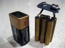
I’m using a 4-channel 5V relay module, powered by the Arduino’s 5V pin (the Arduino itself is powered by a 9V battery).
The pumps are also powered by a separate 9V battery (because they are 6-12V pump), connected through the relay’s NO terminals.
The issue:
Everything seems to work fine for the first few uses (regardless of which button is pressed), but then I start encountering random and erratic behavior:
During a cycle (e.g. AC), the first pump activates for 3 seconds, followed by a 500ms delay, the relay is clicking properly but the second pump fails to start.
In the worst cases, pressing any button causes all pumps to turn on continuously, the Arduino starts blinking erratically, all relay LEDs turn off, and the system becomes unresponsive. I have to reset everything manually.
Before I share my wiring, code, and schematics in detail and take up your time i wanted to ask: Has anyone experienced similar behavior with relays acting unpredictably or “going rogue”? Any ideas, route cause or leads would be greatly appreciated!
Thanks in advance for your help!
I will share a quick video about behavior i've observed soon.
80 Replies
-- Links --
Arduino : https://www.amazon.fr/dp/B01JD2Z5XW?ref=ppx_yo2ov_dt_b_fed_asin_title
Pumps : https://fr.aliexpress.com/item/1005005792284115.html?spm=a2g0o.order_list.order_list_main.17.20a15e5biV40a4&gatewayAdapt=glo2fra
Relay : https://www.amazon.fr/dp/B0DSLL2N7G?ref=ppx_yo2ov_dt_b_fed_asin_title
Buttons : https://www.amazon.fr/dp/B09MBQSM44?ref=ppx_yo2ov_dt_b_fed_asin_title
ELEGOO Carte Starter Kit de Démarrage Super avec Guide d'Utilisati...
Joystick
1 X Module de récepteur IR
1 X Télécommande infrarouge
1 X 6v DC moteur
1 X Module de conducteur du moteur pas-à-pas Uln2003
Lot de 24 interrupteurs à bouton-poussoir momentané 16 mm assorti...
Type de bouton : normalement ouvert lorsqu'il n'est pas pressé, il est en état d'arrêt et l'interrupteur s'allume lorsqu'il est pressé. Auto-réinitialisation : relâchez et débranchez
My first guess is the problem comes from using 9v batteries, probably the worst source of power for any project.
Oh crap, so what do you suggest to use ? I instinctively used the 9v battery because it was included with the training kit. In addition, my wish is to make my thing mobile and turn on via an on/off button and therefore no more power without a mains socket, but that might be too presumptuous?
a 6xAA battery is also 9v, but can provide significant current for a period of time.
pumps especially will draw significant current.
if your power supply (9v battery) is asked to supply more current than it can the result is the voltage drops, causing all sorts of mayhem on the Arduino.
Oh yes, I understand! So, in order to check this, I could first try using a 9v 1a transformer to do my tests (before considering a mobile version using batteries)? Would that be a good idea?
Something like this ? https://www.amazon.fr/gp/aw/d/B00VL1KQ3I?ref=ppx_pt2_mob_b_prod_image
Amazon.fr
Amazon.fr
those are "AAAA" cells, they can supply only a trickle of current compared to AA cells
yes, always best to design on mains power. once it works you can measure how much current a project needs, then size batteries as needed
9v @ 1 amp may or may not be enough to run your pumps
the Uno needs about 100mA itself, the relay coils need power, the pumps need power...
In documentation its written, reccomandation 9v-1a or 12V-1a that why i suggest that try but i understand your meaning.
1 amp per pump?
Yes for one pump, but i Never used them in a same time, always one by one with a minimum 500 ms delay
I'm wrong ? Lol
just as "best practice", design a power supply that can handle 150 - 200% of max load
So any suggestion of supply /transform ? (4 pump 9v-1a, 1 relay 4 channels et and 1 uno)
if you are only running 1 pump at a time then 2 amps is about 200% of maximum draw
I will try this, thank you very much for your answers and your time ! (I will let you know 😊 😇)
np, have fun, sounds like a cool project
I will share it when it's done !
@AnonEngineering , hello, so i'v receive my supply 9v-2a, the pumps are working better but i still have the problem 😢 🤪.
what problem, exactly?
all that erratic business?
I'd suspect button wiring
I've made a video but too heavy to send in this channel
how are the buttons wired? pull up? pull down?
Pull down, and i tried to manage the debounce by code.
We transfert link, Inc 🤗
I will wait for your opinion but I am thinking of buying a second relay because I have the feeling that the second channel is defective.
VID_20250826_180405.mp4
1 file sent via WeTransfer, the simplest way to send your files around the world
test the relays all by themselves, using simple code
hardware usually isn't the problem, bad code often is
Of course, I tested them one by one and all on table before starting to build my machine but, when my machine was finished, this kind of chaos/bug appeared
The code.
do all 4 channels behave with simple code?
if so it's not a hardware problem (though it might still be a power supply problem)
Yes, all channels was working perfectly before starting the prototype construction
but i'm thinking about my bad use of supply and damaging them 😅
then likely a code issue
I'm at work ATM, I'll take a look later
this seems to work, only the pin numbers were changed
https://wokwi.com/projects/440377107161322497
Thanks for you time, so my code seems good ? So what could be my problem 😢
- Bad wiring?
- Poor connections?
- A side effect such as a short circuit?
if the sim is doing what you want then the code is good.
so my next prime suspect is wiring which includes things like the pumps injecting electrical noise into the system
if you leave the relays connected but do not power the pumps does it seem to work well?
Oh, good idea to target this test to eliminate leads! I'll try that tomorrow morning and let you know 🙏
Hello @AnonEngineering how are you ? Good news, you've highlighted where the problem lies !
Everything works perfectly if I disconnect all the pumps !
E went a little further I connected each pump one by one and the problem occurs whatever the pump connected !
For my understanding, do you think you know what could be happening ? And how to correct this ? (add capacitors ?)
if you power only the pumps with the 9v supply and power the Uno with USB does the system behave?
In the end some capacitors will likely be needed to fix the problem, either small ones at the pump motors, big ones at Vin, or both.
Yes same issue when i supply separatly Pumps and Uno+Relay.
If I need to add capacitors
Where exactly should I insert them? Series or parallel ?
And what size would you recommend for a 9v / 1a or 2a power supply ?
And should i use NPN or PNP transistor (best practice) ?
After some research I'm assuming that NPN 90V / 1.5A connected in serie on the ground (or PNP to the voltage) to each pump is a solution for me ?
- Transistor NPN BD237 is a good choice 80V - 2A ?
- or PNP BD140 80V 1.5A ?
On the other hand i'm not sure about the resistance to apply on the third pin of transistor ☹️ , i found some formula like :
hFe = 𝛽 (gain) = Ic / Ib
Rb = (VS - VBE) / Ib
Ic = Collector current worked based on pump specification -> 0.5-0.7A -> average = 0.6A
Ib = Supply base current -> 1A
VS = Supply base voltage -> 9V
VBE = drop voltage across the base emitter junction -> 0.7V
hFe = 𝛽 (gain) = Ic / Ib = 0.6 / 1 = 0.6
Rb = = (VS - VBE) / Ib = (9 - 0.7) / 1 = 8.3
8.3Ω seems ridiculous, i'm doing wrong ?
I need your expertise @AnonEngineering 🙏 😅
Transistors instead of the relays won't help.
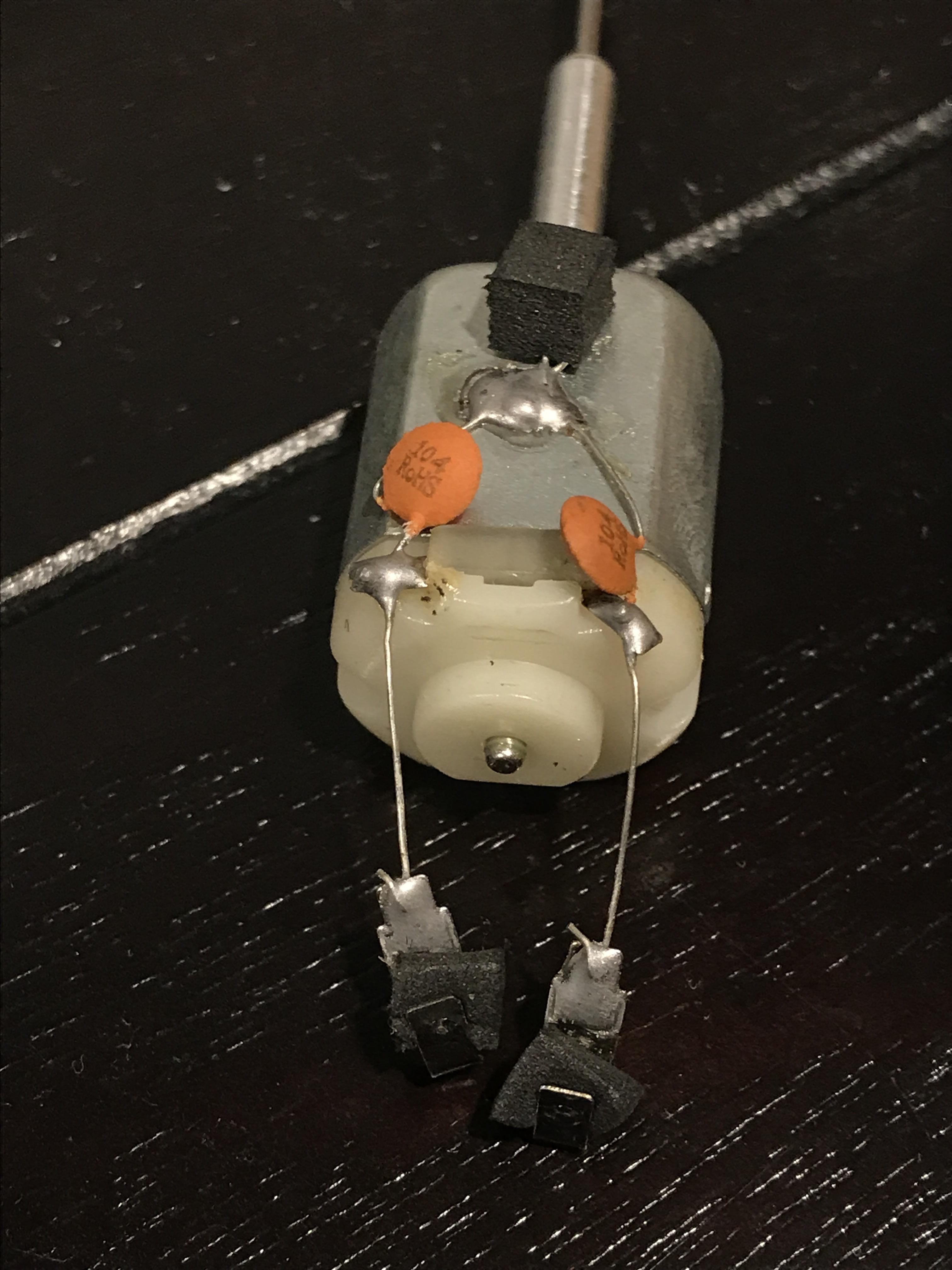
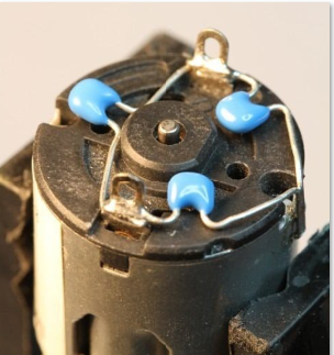
I'd start with some 100nF capacitors from each lead of the pump motors to ground
then add a 100 - 470uF electrolytic across the Vin terminals of the Uno if needed
a photo of your setup might be helpful
Haven't you watched my video sent from We-Transfert where I present my machine and my initial problem? OK, I'll send you my zoomed configuration
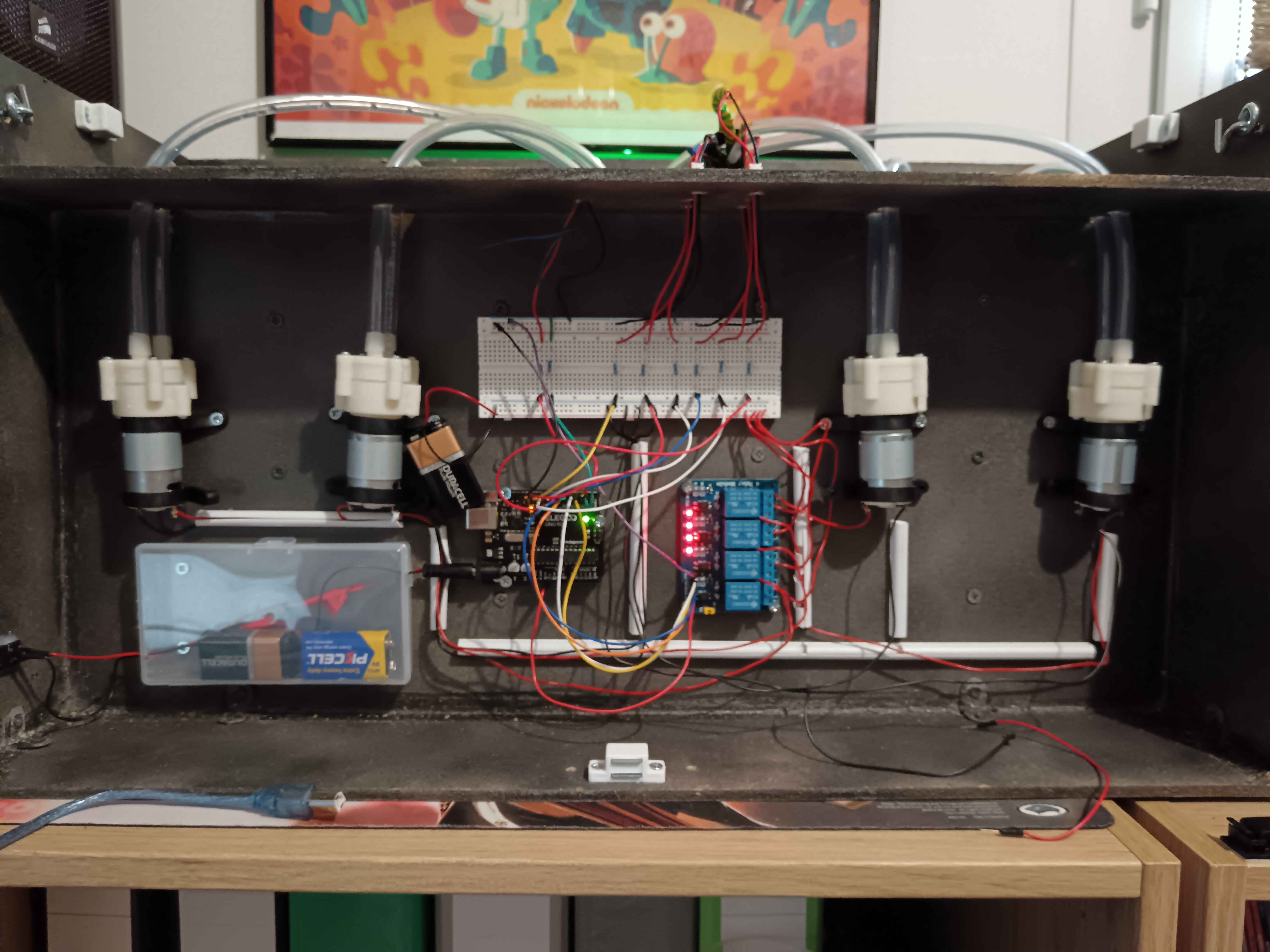
Sorry it's a bit of a mess because I took all the cables out of the conduits in order to review everything and look for the problem 🤗
The battery suspended at the top left of Uno is what only powers the pumps (for testing) , and the supply at Left (inside plastic box) supply the uno / relay.
in the video:
it looks like the 9v 2A supply is only going to the Uno?
It looks like pump 9v is coming from the Uno?
yes in the video i used the vin to supply the pump (i know its forbidden arduino is not a power supply 😛 ). But even if i used a dedicated supply for the pumps the issue occurs
ok, if you power Uno with USB and pumps with 9V/2A you still have the issue?
Unfortunately, I cannot test this because my 9V -2A transformer is a jack (I would have to cut it to test it)
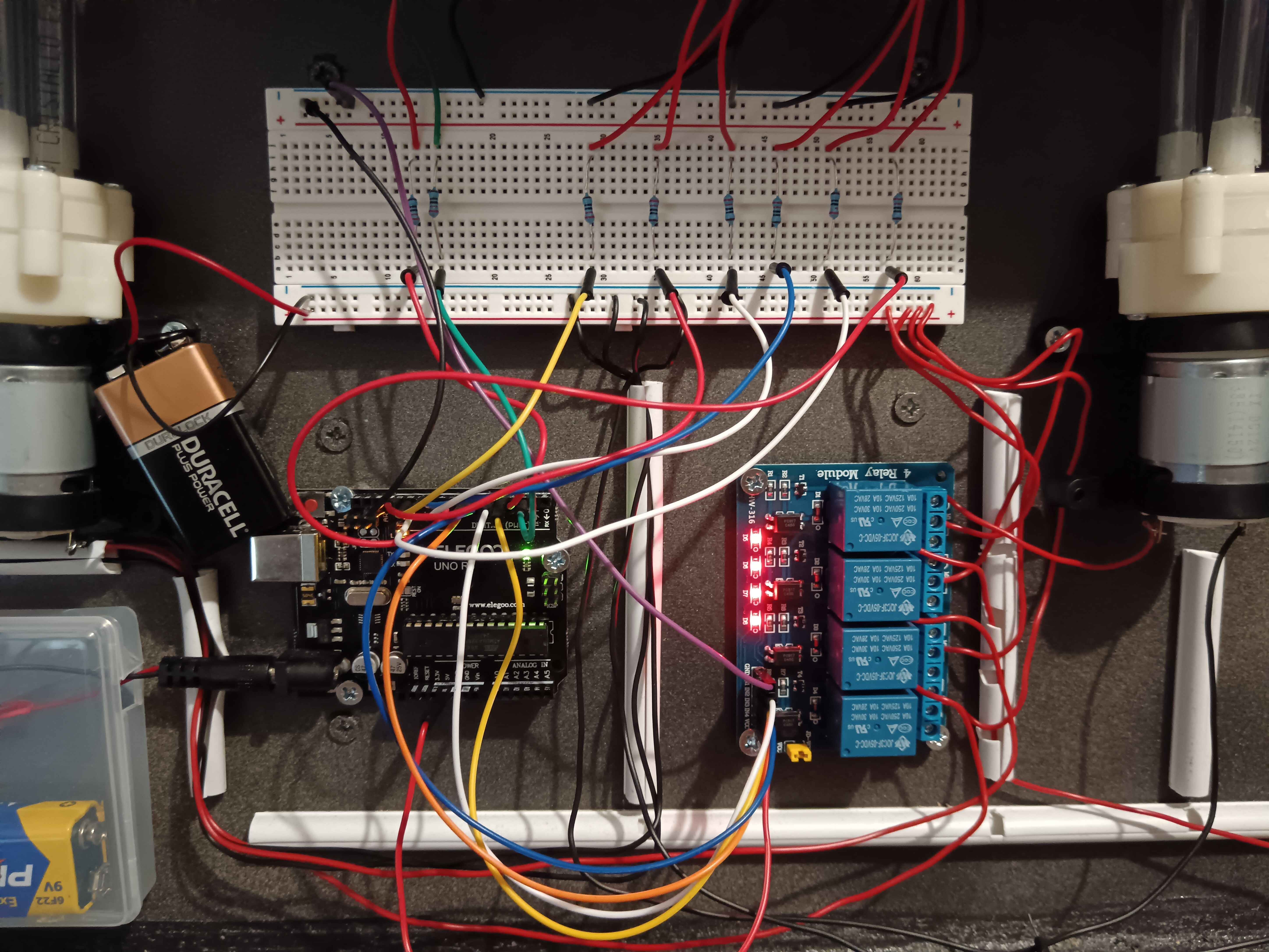
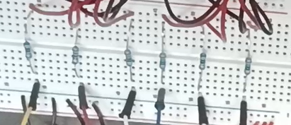
what are the resistors doing?
that why i used the battery 9V for the test
The top wiring is the 6 buttons management, so one resistor for each
there should be no resistors on your buttons https://wokwi.com/projects/440377107161322497
This is leftover from a test.
5 days ago there was none here (I suspected a noise coming from the button like a bounce or something like that)
the LEDs need resistors...
ok, led have resistor too at the moment, but i'm gona remove them from button no problem
try to wire the buttons exactly as shown in the sim
if that doesn't help get some small 100nF caps and wire them to your pump motors as shown above
basically, with
INPUT_PULLUP the button goes between the pin and ground
route the wiring for high current noisy things (pumps) as far away from input wires as possibleI already tried without resistance on the buttons, it was my main definition of the prototype and my first attempt, I tried to put some of them to look for the cause (by fumbling and trying weird things maybe ^^)
i will try to add capacitor i guess
in serie on the volatge ?
if you don't want to cut your power supply use something like this
yes i must buy it !
capacitors block DC current, you wire the caps across (parallel), not series
so between the 2 pins of the pump ? (between ground and voltage)
leave the pump wiring as is, add a cap from each terminal to the case
one across both pins might help too
it's hard to know where the noise is coming from without an oscilloscope
so you mean on the breadboard directly between + and - ?
no, right at the motor, you want to bypass the noise before it travels along your wires (which act like antennas)
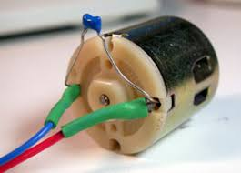
I have to solder a 100 nf capacitor directly between the + pin and the - pin of my pump?
yes like this , OK !
you could start with that yes
it may need more, but it's a start
in a commercial product they go to great lengths to isolate high current and low current power supplies
filter caps, ferrite beads, wiring, etc
yes for me now it's more understandable
yes step by step , thank you !
step by step is the key!
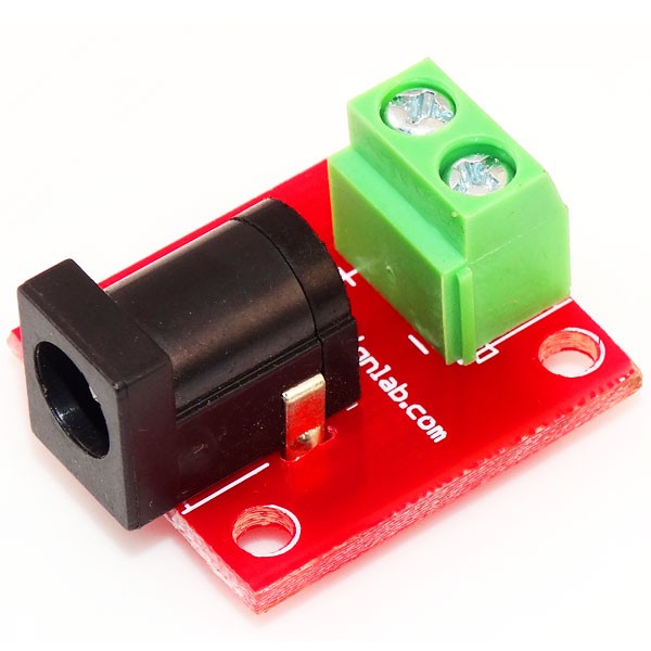
About this what is the real name please ? (when i put uino jack module on amazon i didn't found them :/ )
i searched "dc jack breakout board", just make sure you pick one that has dimensions that match your plug
honestly, the wall adapters are so cheap, wouldn't it pay to just cut the plug off?
the supply 9v-2a cost like 10 to 15 euros / dollars from my country :/
not that cheap
yikes, only a few USD here (or at least they were before tariffs 🙁 )
I'll see, maybe I'll cut it anyway, as long as it works it suits me 😛
just checked, yeah now they are $10 - $15 🙁
sadly the power of inflation
where are you located ? english country ?
near New York City
but far enough away I have bears in my yard 🙂
exciting and scary at the same time lol
I'm coming from France (near rabbits and vines ^^), thank you again i will let you know about capacity wiring result
ok, bon chance!
@AnonEngineering Hello , how are you ? I hope y'oure doing well ?
After a big problem with the delivery of the capacitors, they finally arrived yesterday. Today my first tests are very conclusive, with the 9V batteries still the same issue but it occurs a little less often (following your advice I must forget the idea of 9V batteries), on the other hand with the 9V 2A transformer it works wonderfully for the moment I pressed about 20 times on the cycle button without noticing any crazy behavior. I will still continue my tests et let you know.
glad to hear it helped!
yes, thanks a lot ! In case I would like to insist on the fact that my machine can be "nomadic" and therefore work with a battery, what could I turn to to get out of 9v 2A?
a 6xAA battery pack produces 9v and can provide 2A in short bursts.
try that, it may be good enough, but if the batteries drain too quickly you'll need to go to a LiPo / Converter / Charger system which will increase system complexity
The snubber caps have zero series resistance they may break over time potentially?
Usually people use flyback diodes or I have seen RC snubbers, zener/TVS diodes. I have only seen capacitor snubbers on very small motors. This motor appears to be small enough to get away with it I think. Only a problem if the caps die.
Thank you for your advice. I will keep an eye on the capacitor durability.
It’s probably fine if the capacitor has the correct ratings. I would think it would be better to have a next to zero impedance snubber for noise reasons. It’s just something I have never seen before
You are probably having problems with the current rating of the power supply.
The back EMF from a dc inductor I have seen in the hundreds of Volts range with a small voltage power supply. It’s the first time I shocked myself because I was working with 9V. I did not expect the back-emf to reach hundreds of volts (I was like 12, this is many years ago) I utilized the back emf from a small steel core inductor as an impulse to drive a long fluorescent bulb. Dc motors probably reach something like 20-40V on the back emf. Definitely would cause the Arduino to glitch out. Audrinos crash from much less EMF.