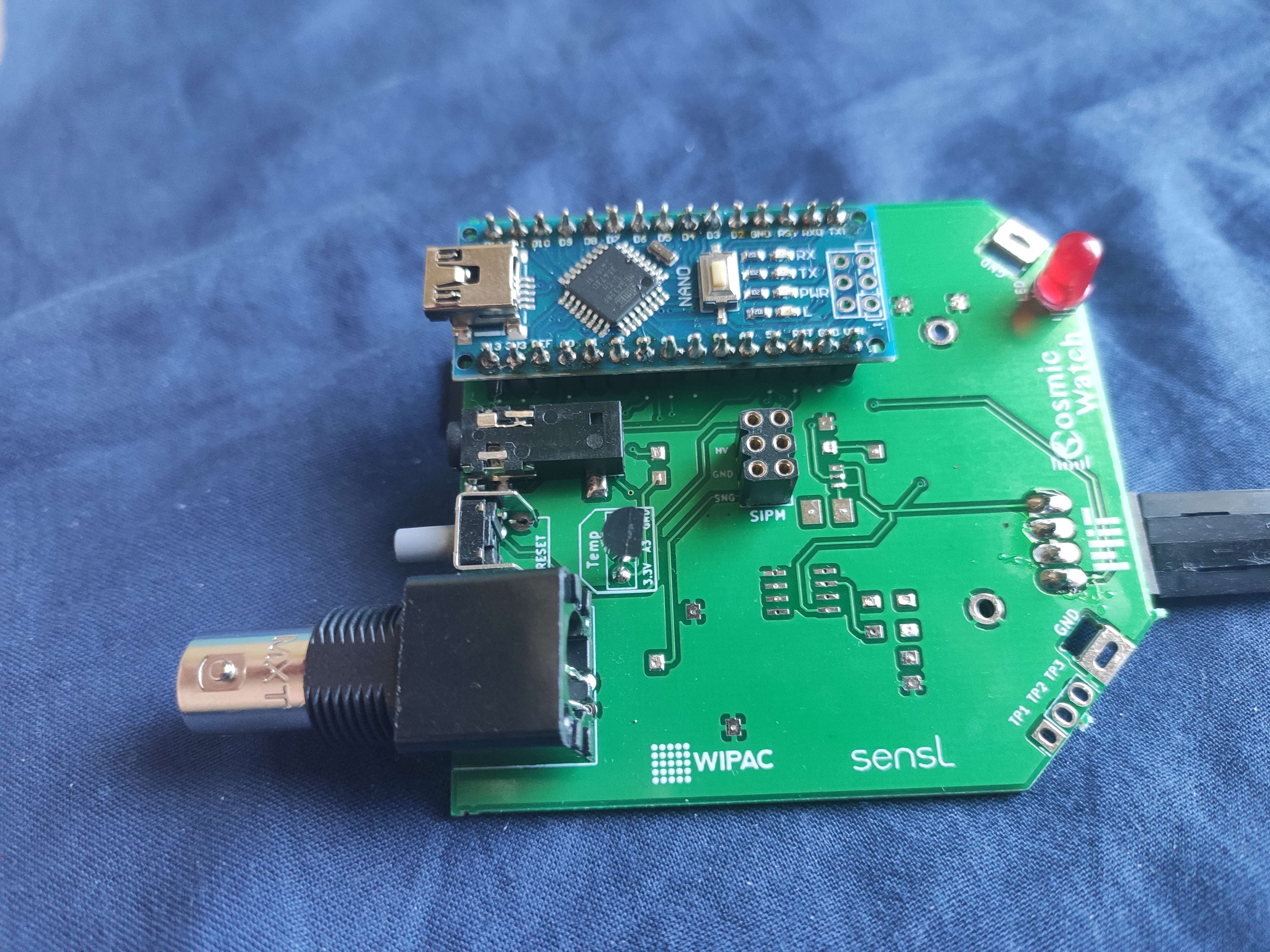
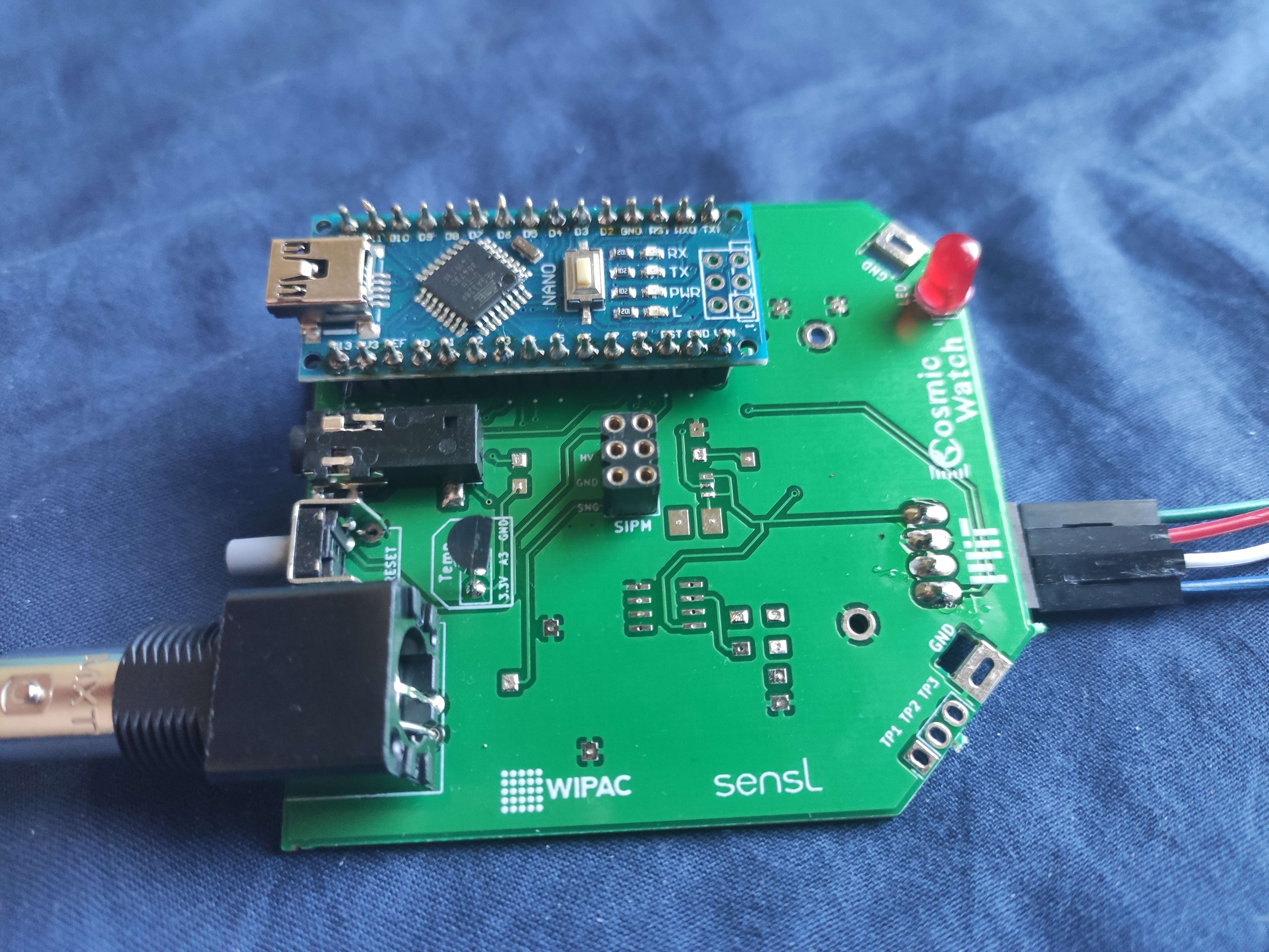
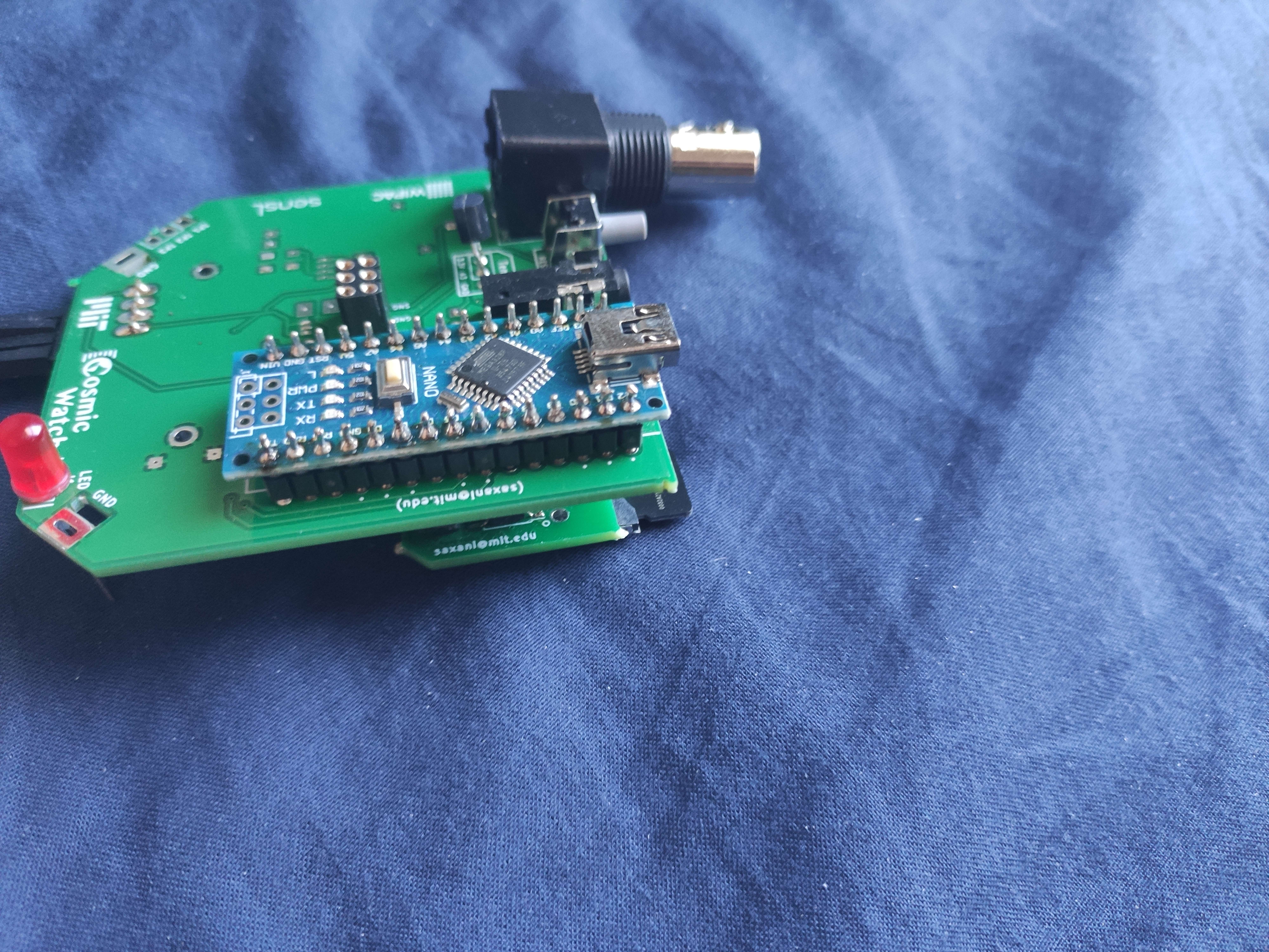
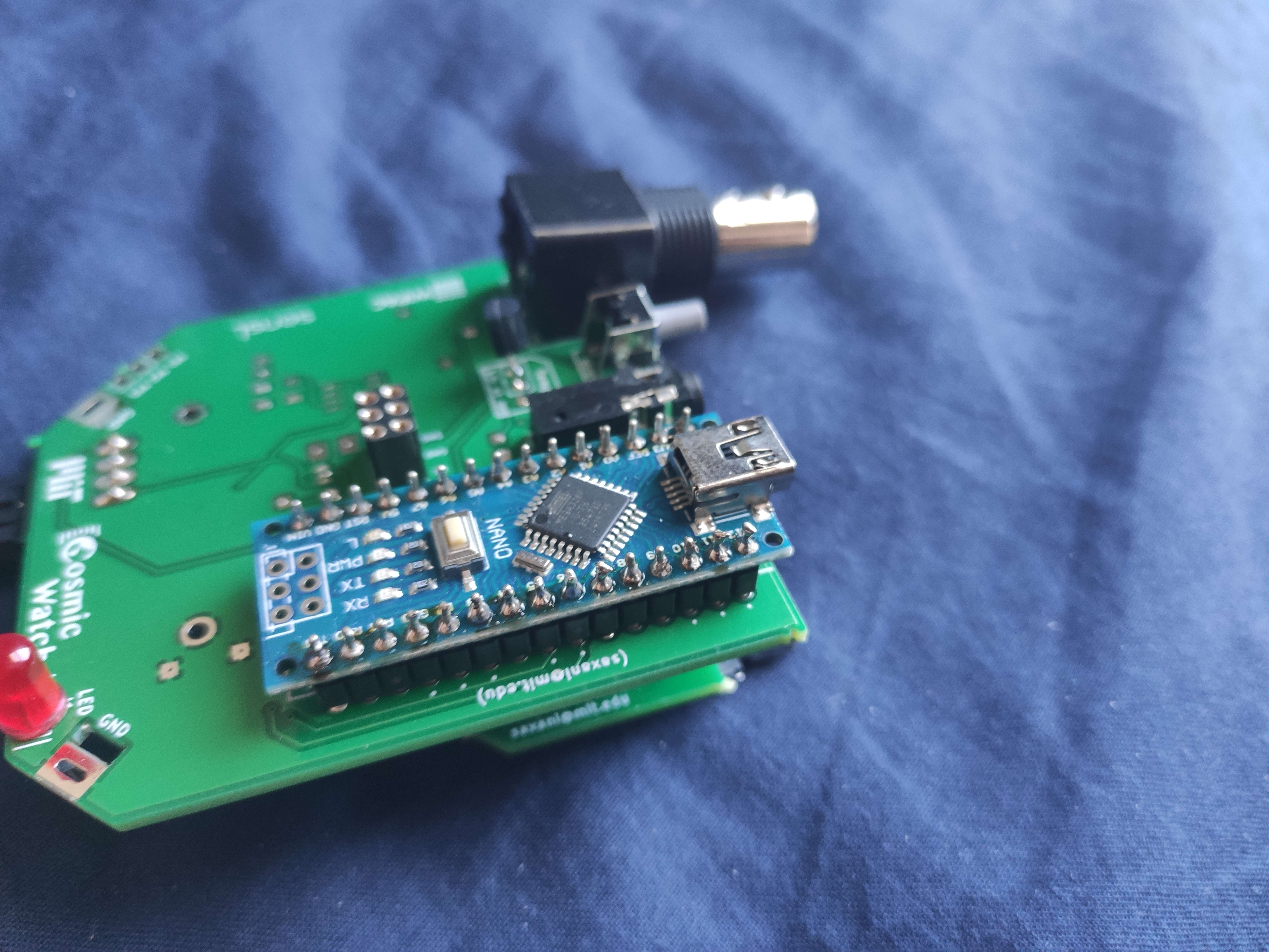
Troubleshooting Cosmicwatch's Muon Detector
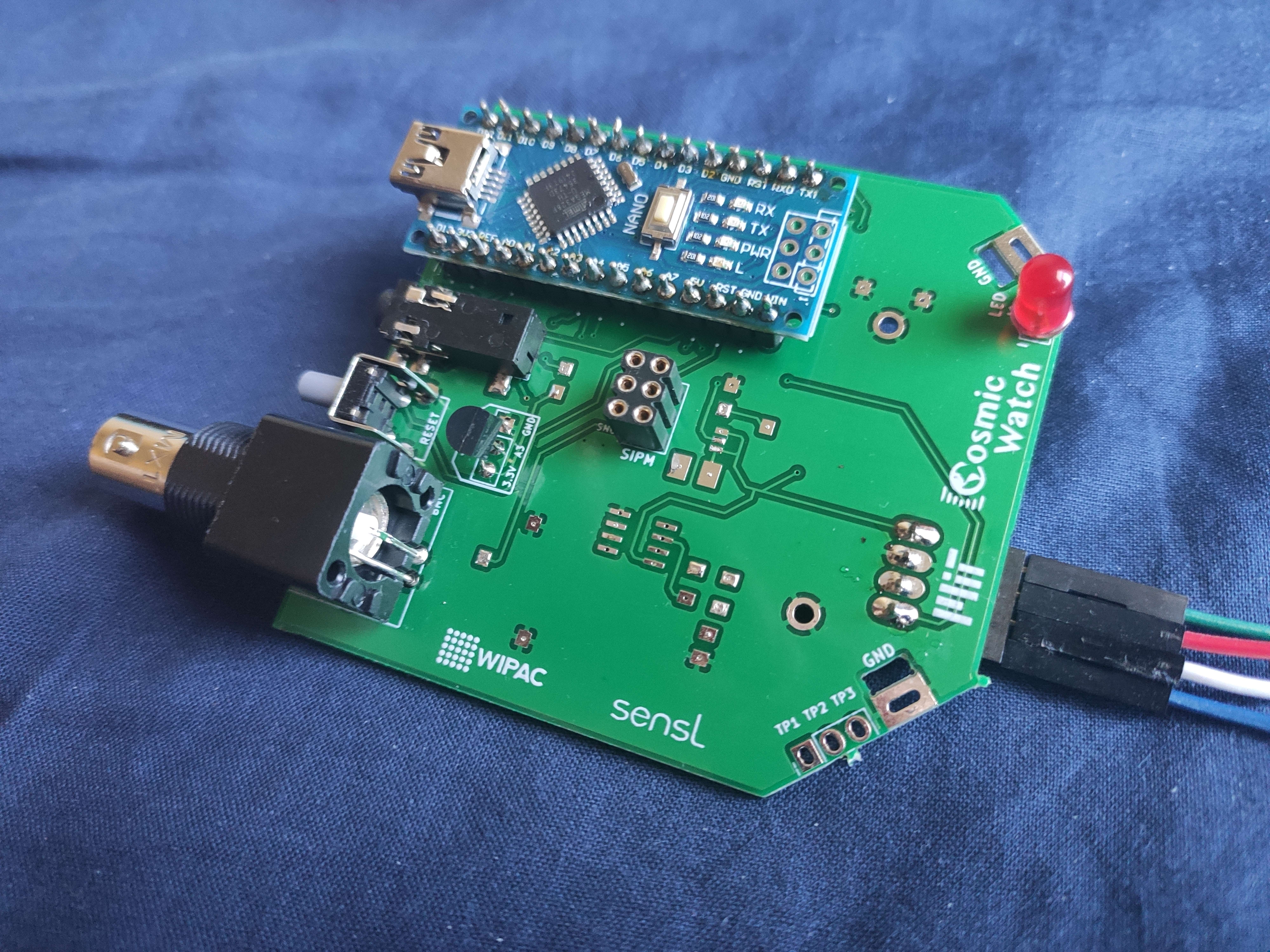
So I recently finished building a muon detector created by Cosmic Watch (http://www.cosmicwatch.lns.mit.edu/), but it doesn't work. I am not getting any output on the OLED screen nor is the LED flashing. There are three main reasons why I think it wouldn't work:
1.) I used slightly different hardware on some occasions, because the original was unavailable
(slightly different chip in terms of the name, but it apparently was just a newer version, still I will compare the datasheets to make sure the pin locations are the same);
(slightly different resistors/capacitors, same resistance/capacitance, but different voltage or wattage values);
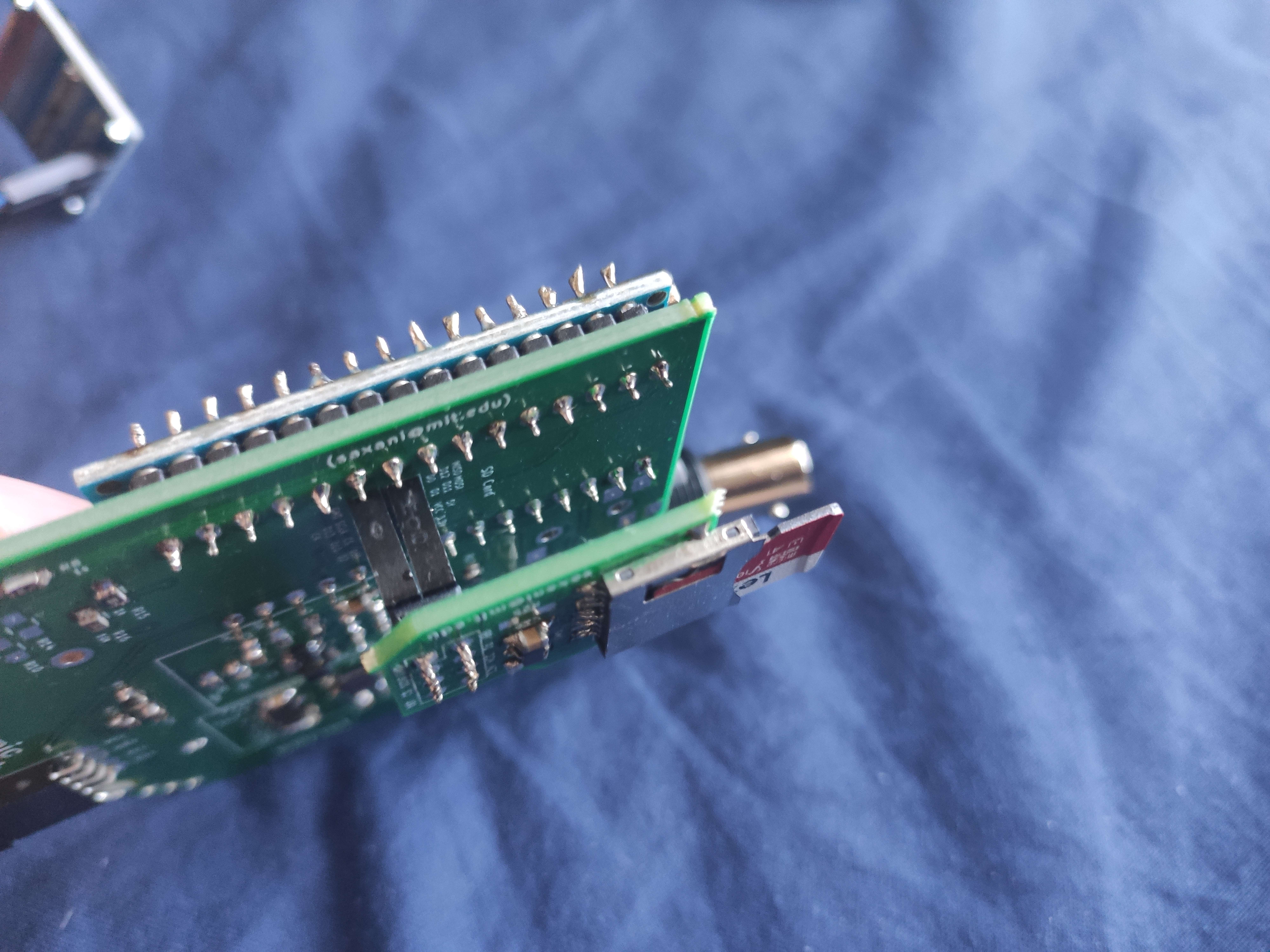
(the OLED screen's pins are in a totally different order than those on the PCB, so i used wires to redirect them)
2.) The code might be wrong or not suited for the specific detector I built, or might be missing some functions. When I verified it (clicked the verify button), there were no problems, I also downloaded the necessary libraries.
3.) The solder might not be sufficient, or might be too much. What are some signs I should look out for to determine the quality of the soldering job?
Code I used: https://github.com/spenceraxani/CosmicWatch-Desktop-Muon-Detector/tree/master/Arduino_Code
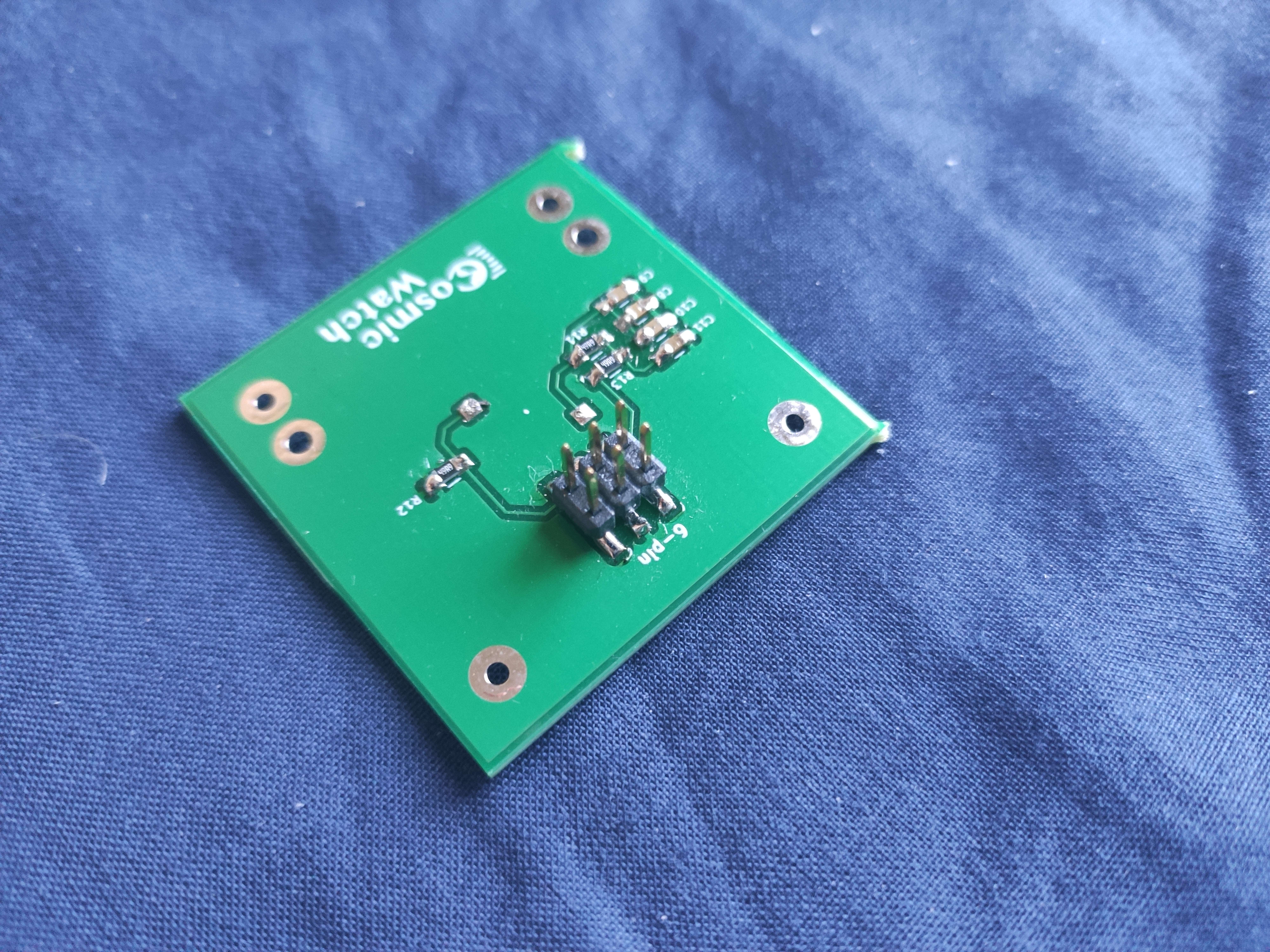
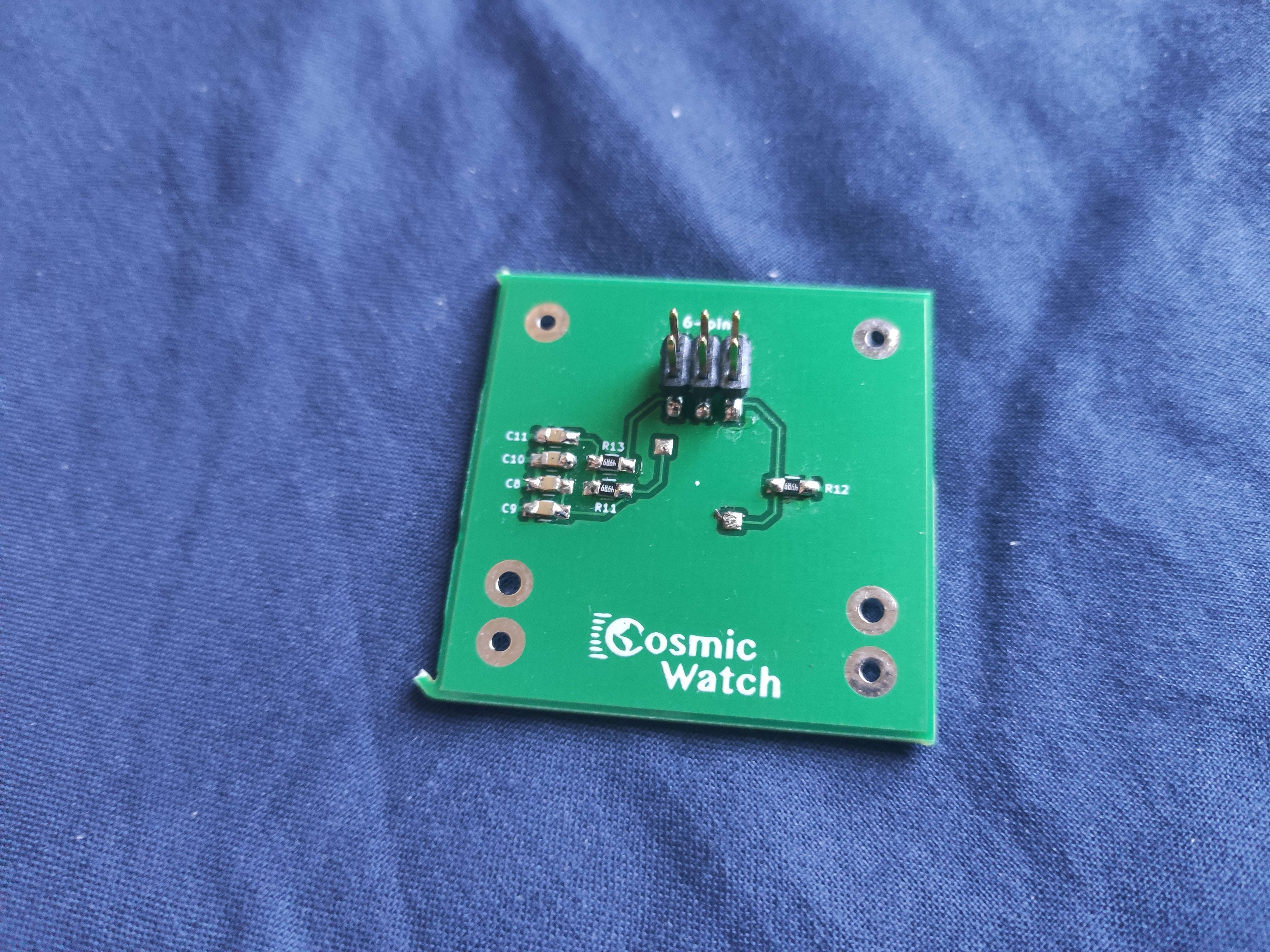
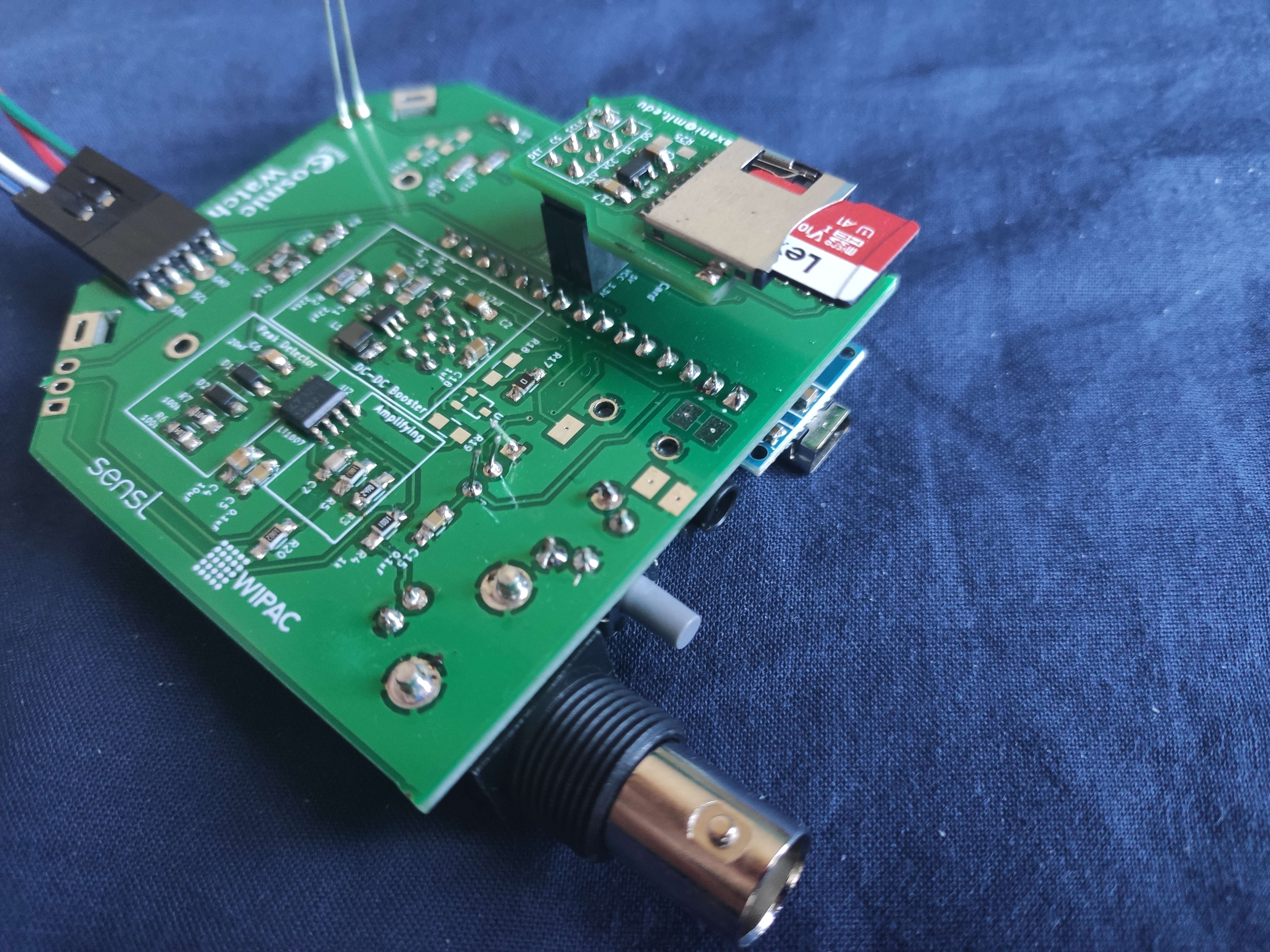
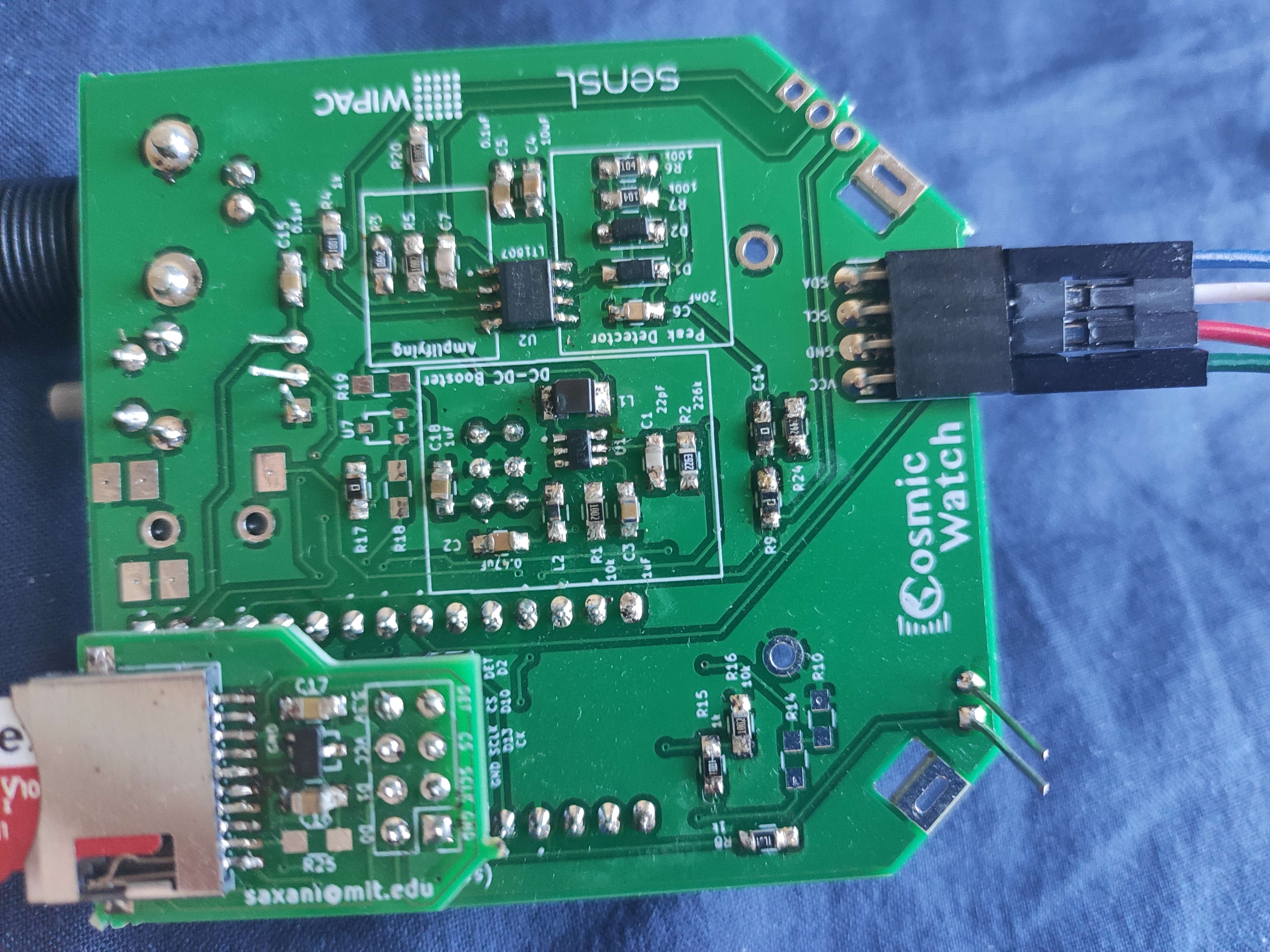
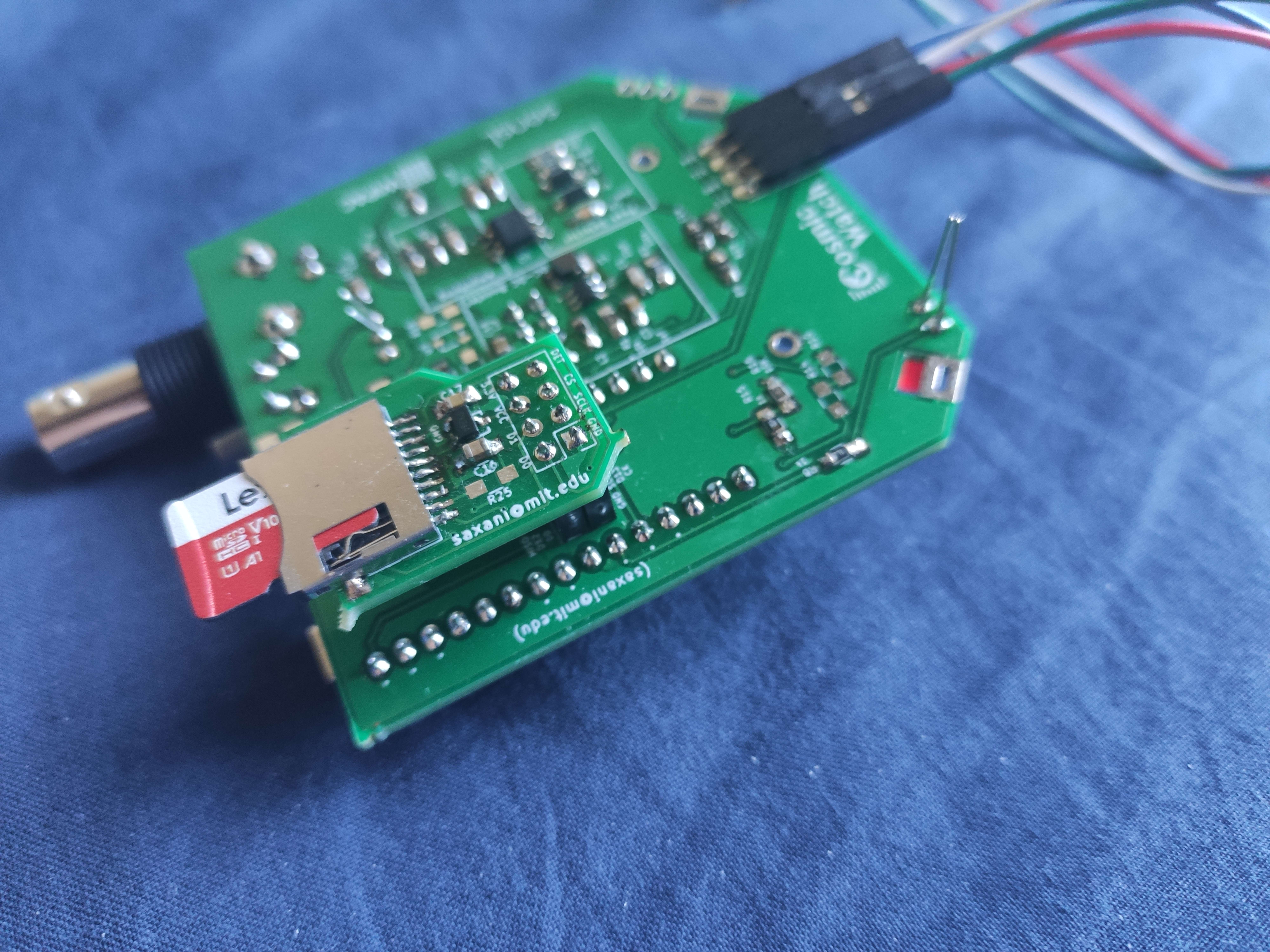
Detector components list: SMT_reference PDF linked below
PCB files: https://github.com/spenceraxani/CosmicWatch-Desktop-Muon-Detector/tree/master/PCB_Files
36 Replies
No, unleaded solder


i see what you mean
there is a strip of something shiny there yeah
i'll try to remove and see if that changes anything
thank you for your help, i will come back with the results later when i have more time
alright
i removed the strip of solder, but it didn't change anything
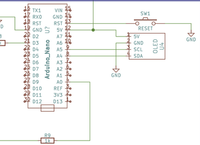
the arduino nano seems to function properly, so does the button (when i press the button, the L light on the nano flashes)
i am not getting any output through the OLED though
i'll have to first troubleshoot through code to test whether the LED and OLED display function
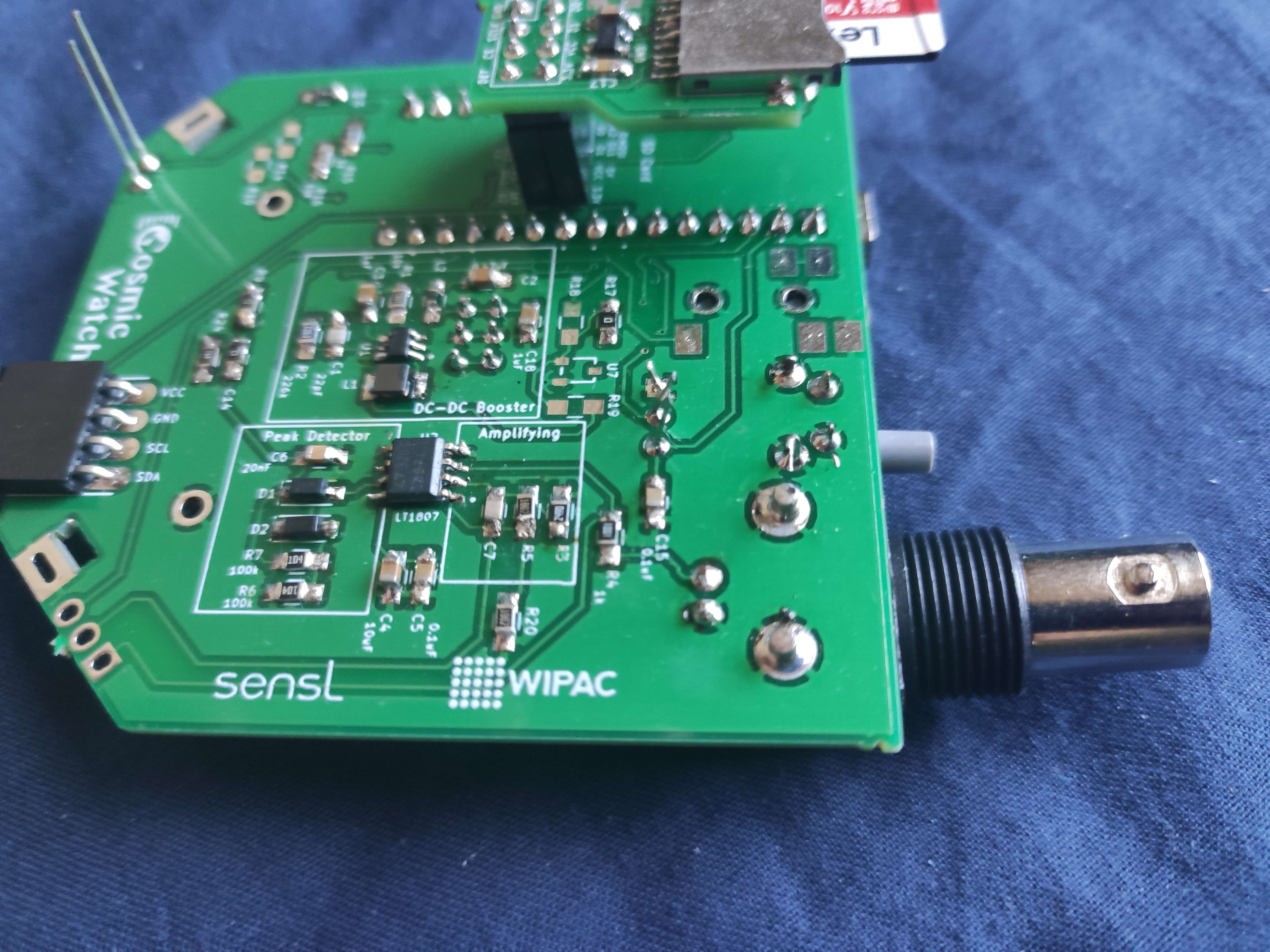
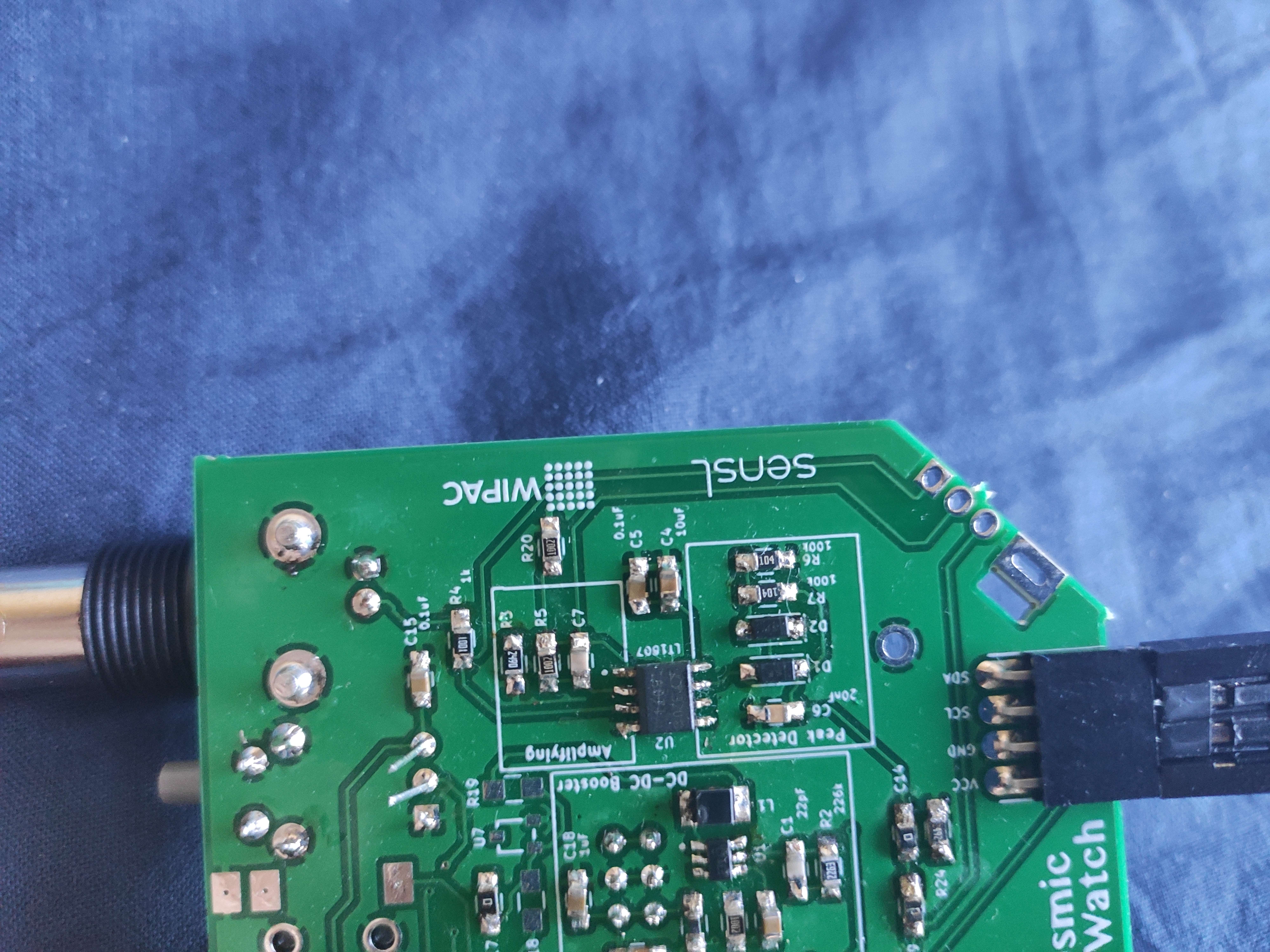
The LED works, it is connected to the Analog 3 pin
having checked the datasheets for the LT3461ES6 chip, the pin configuration is good
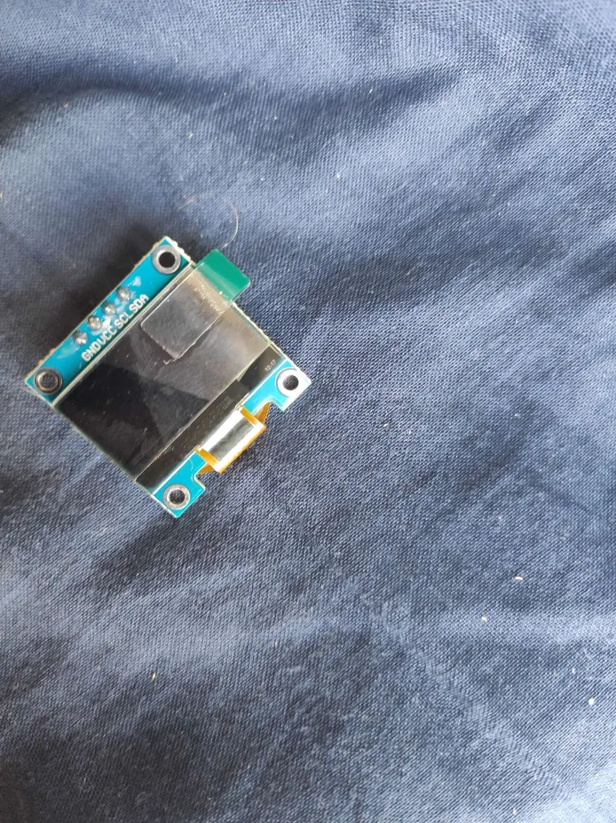
The website says that if there is not output on the OLED screens, then either the manufacturer inversed the VCC and GND pins (which i noticed, that's why the display is connected by wires)
or the screen is cracked/defective
but i doubt 5 of my displays are defective
Can you send the code
For the OLED
@Gabileotank 📎📎📎📎📎
And what OLED screen did you used
the code i used is from the github website, the OLED is meant to be connected in this way:
Uuuh where is the GitHub
at the top of the thread
^
Do you know like the model number of the OLED
Send a picture of both sides of the OLED
This code only works with SSD1306
So OLED
If you used a different OLED the code won't work so then you can either
1. Get the SSD1306
2. Rewrite it in a different library
Come back!!!!!!
i do not know the model, but here is a picture
it's loading...
i am using SSD1306, adafruit version
Hm

well, the OLED seems to be the problem
i used this code
and the OLED is blank
On the
Instead of 0x3C try doing 0x3D
You have a different model but the library should work
@Gabileotank 📎📎📎📎📎
nothing
i'll try to order new models and see what happens
lemme try the same with an arduino micro (and without the circuit)
Ok
well i ended up picking an UNO r3, shouldn't matter
ok
it works with 0x3C
so, it's a problem between the nano and the OLED
perhaps the nano is the problem, or the PCB/circuit
Hm
i'll try to connect the OLED directly to the nano first
if that works, then the circuit/PCB is the problem
It might also be power
Try connecting power to the OLED externally
ok
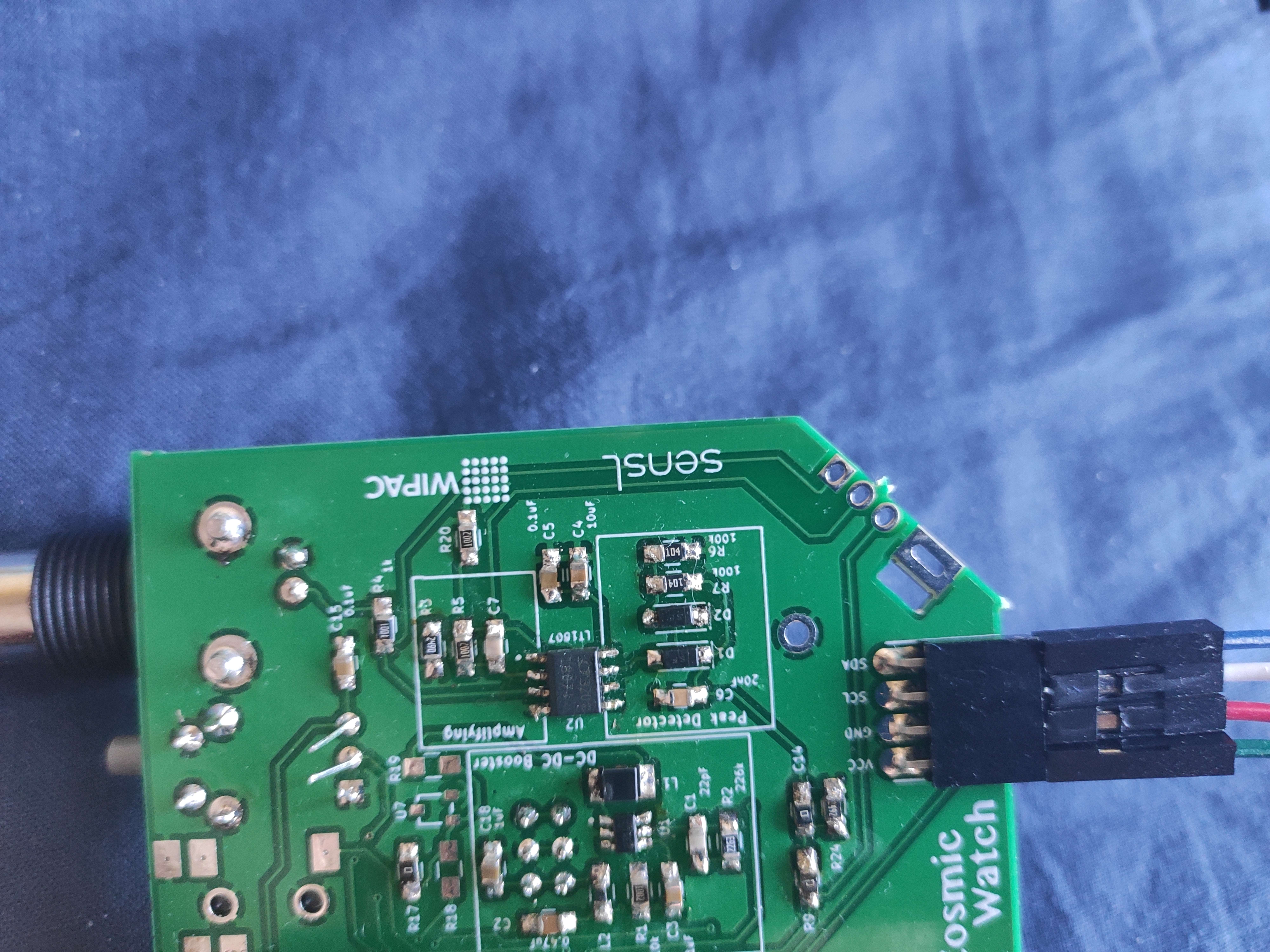
i'll have to solder wires on directly, just tapping the pins with wires doesn't work
will take about 5 mins
Make sure you don't mess up SCL and SDA lol
i didn't, scl goes to a5 and sda to a4
works!
all right, so there is a problem in the circuit
when i plug the 5v and gnd pins back into the PCB, it doesn't work
i'll try to add more solder and see if that does anything
actually, i'll check first what happens when i reupload the muon detector code
yup
works
although i'm not not able to detect any muons
it worked for 4 of them at first, then stuff stopped happening
and to test that, i need an oscilloscope
i don't think we have one at home lol
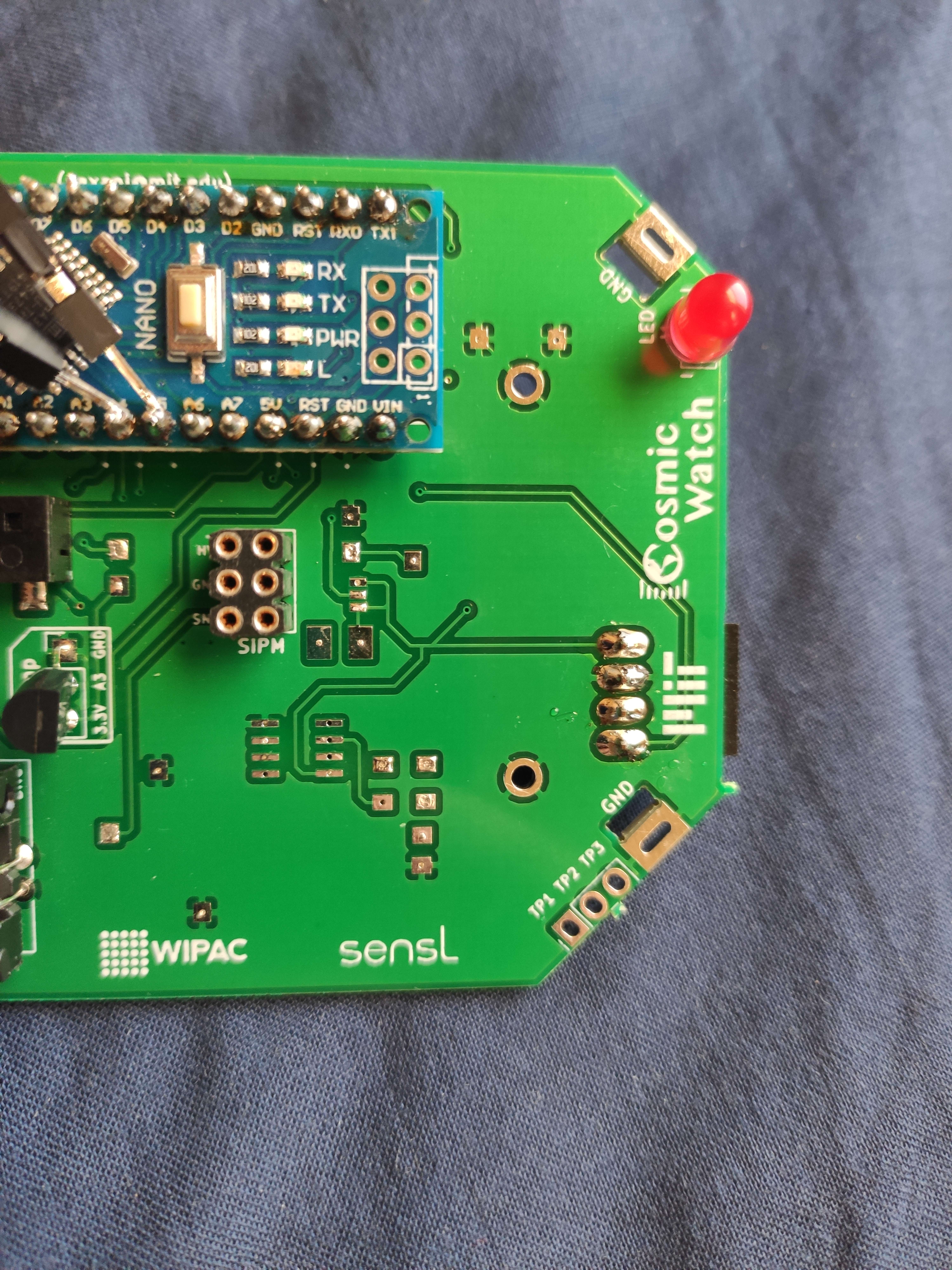
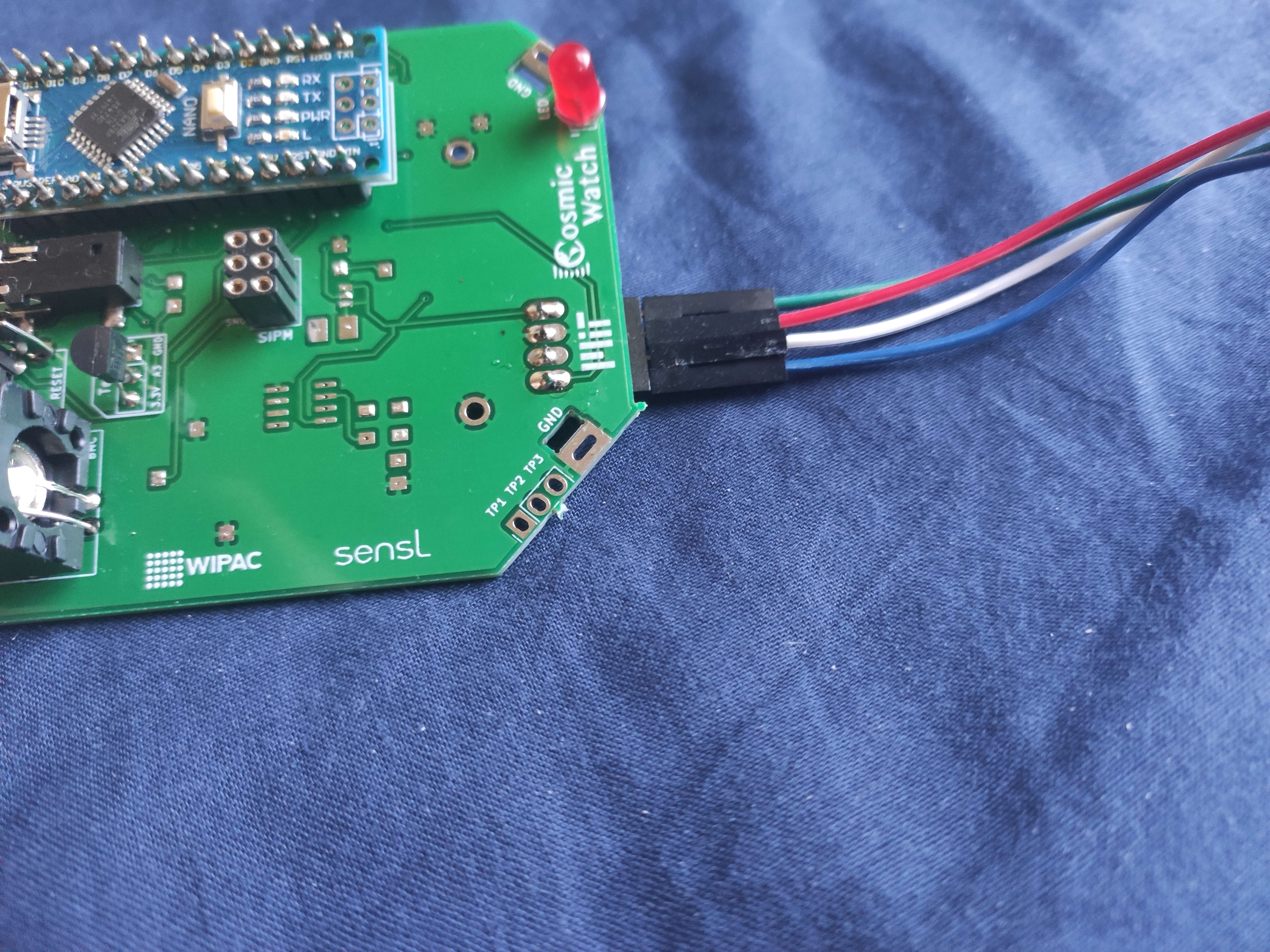
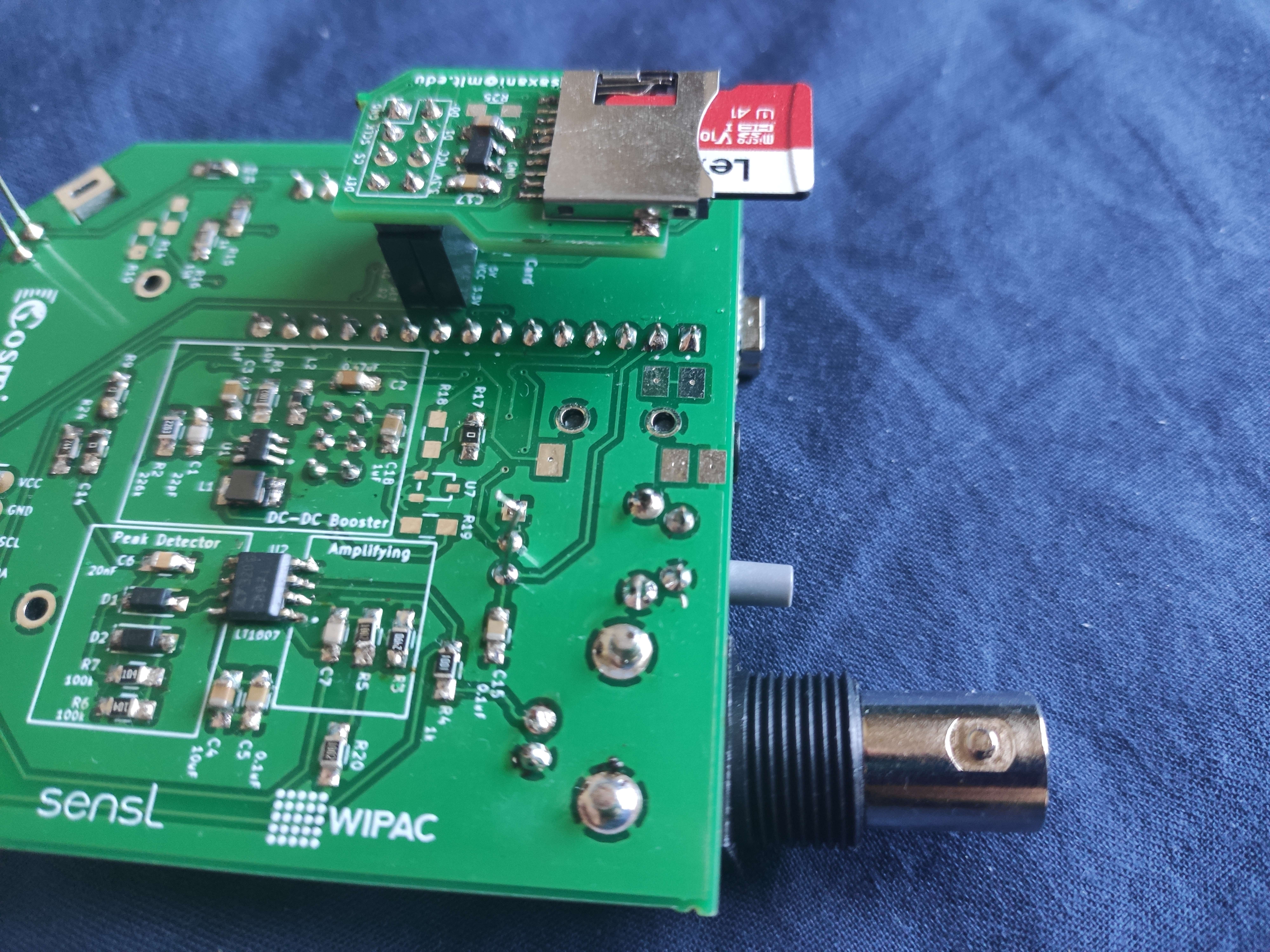
do you reckon that the fact that there are "holes" in some parts would mean there is not enough solder?
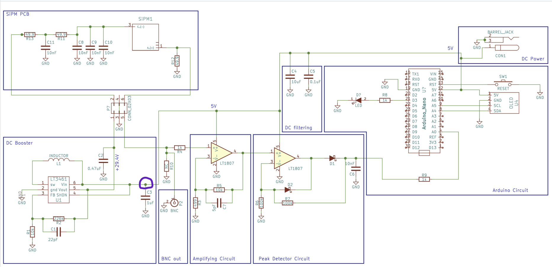
the schematic says the VCC is directly connected to the 5v pin, and it is if you follow the lines on the PCB
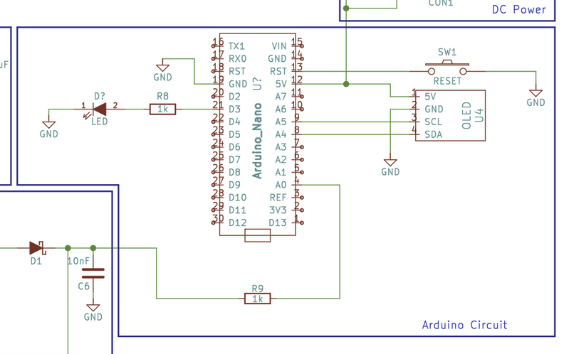
but in practice there is no current going to that VCC pin
and only the VCC pin doesn't work
SDA, GND and SCL do
worst case scenario, since everything appears to work, i'll just connect the 5v directly to the nano by wire
and focus on the other inputs
ok it looks like the whole 5v pin of the arduino nano isn't working...
great...
and it's maybe connected to the SiPM, so perhaps that's why I wasn't getting any detection...
Well, i'm not sure whether the SiPM relies on 3.3v or 5v
it's kinda of hard reading the schematics 😅
although, the voltage seems to need to be amplified, so i'd have to plug it in before it gets amplified
perhaps right before it goes into Vin?
maybe at the purple circle
that's what I need feedback on, since I have very little experience
@Gabileotank 📎📎📎📎📎 whats your question? the purple circle is a 5v rail if thats your question.
My question is whether i can plug a 5v cable from another power source (second arduino) to test whether the circuit of the SiPM works
Since the 5v needs to be first amplified to 29.4v
Oh. I got warned for chat flooding lol
And since the 5v of the Arduino nano seems to be broken
well you need 5v and ground on that line, I doubt it matters where it gets it from, but yeh, you need 5v on that line. If your flooding chat. Just any time you think.... OH and I need to say... then just go up and edit your last message. you dont want to end up getting timed out.😰
Yeah good idea😅
Well, I'll get back to it tomorrow, it's pretty late now. Thanks for the help.
FYI the bots hit us also. so thats why we know. we get timed out and caught for saying bad words, and what gets me often is I used to say "cool" all the time when I would walk somebody through a long process, like do you have the com port? cool, did you get the wire hooked up "cool" is the led lit? cool. and the third cool would time me out all the time as the bot thinks I am spamming cool. and OMG if I am heloing 3 people on seperate channels at the same time..... I have been kicked/banned before. 😄