I just melted my ground wires and I don't know why :(
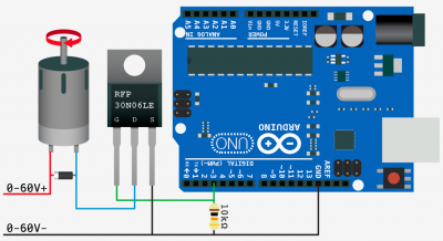
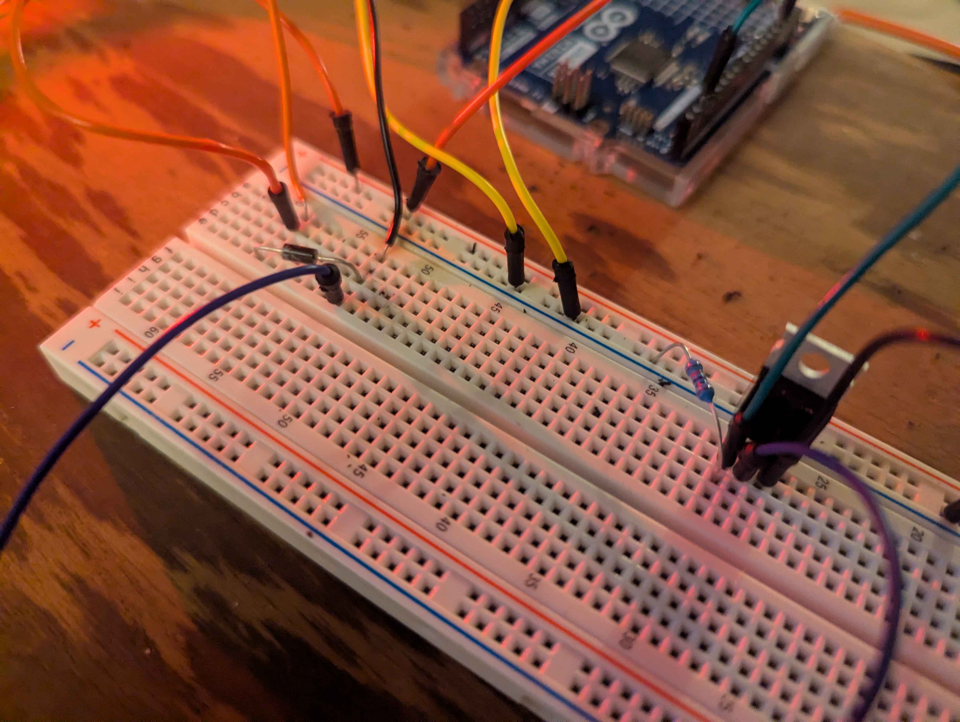
Pretty embaressed honestly. I just tried to create this simple circuit exactly...
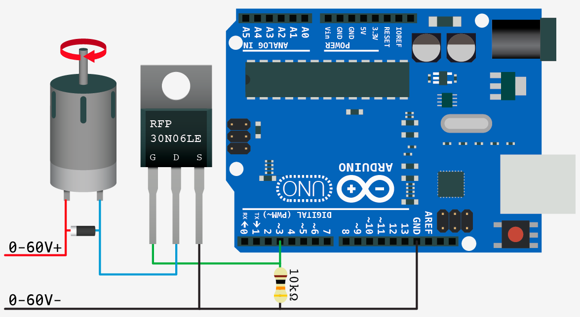
http://adam-meyer.com/arduino/N-Channel_MOSFET
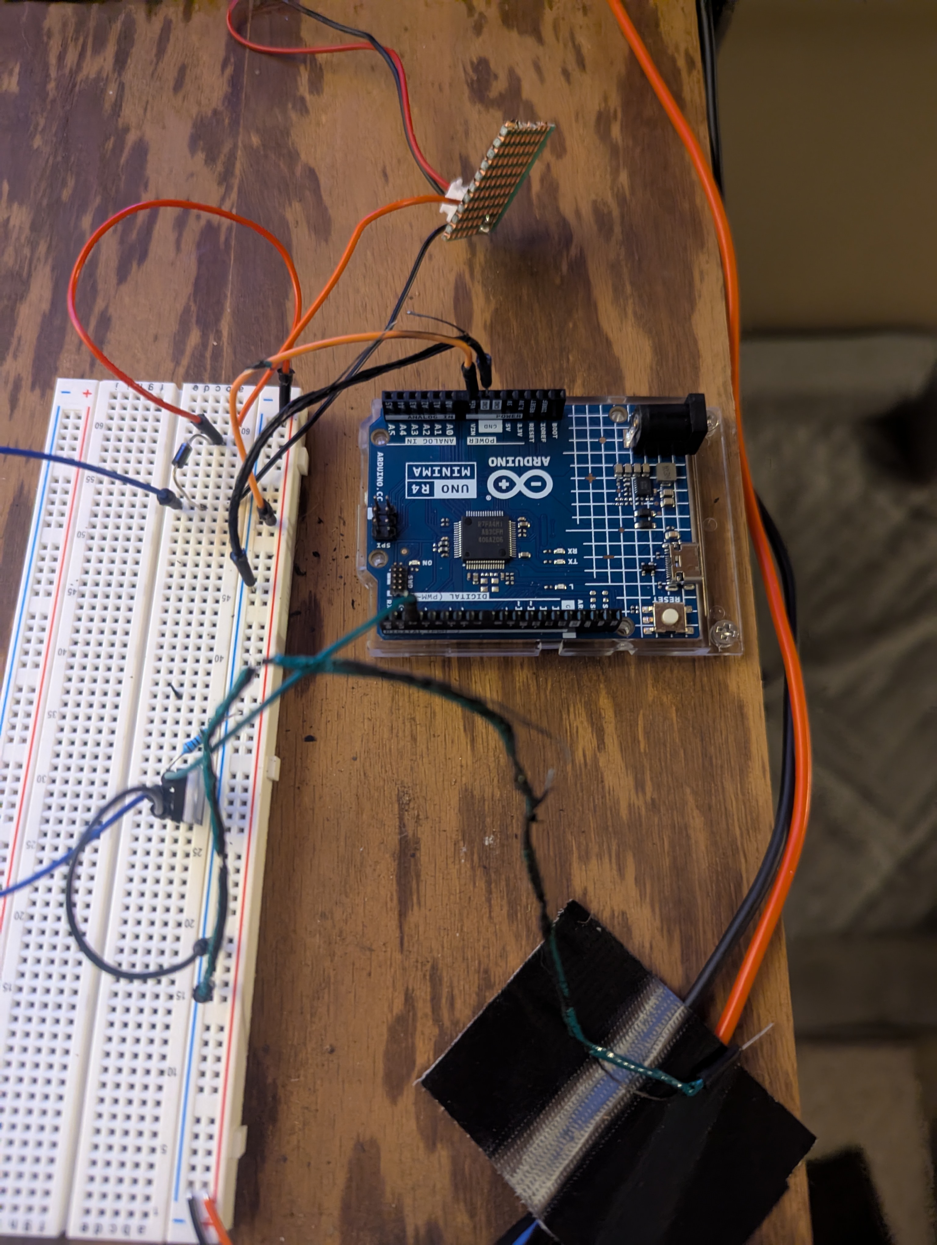
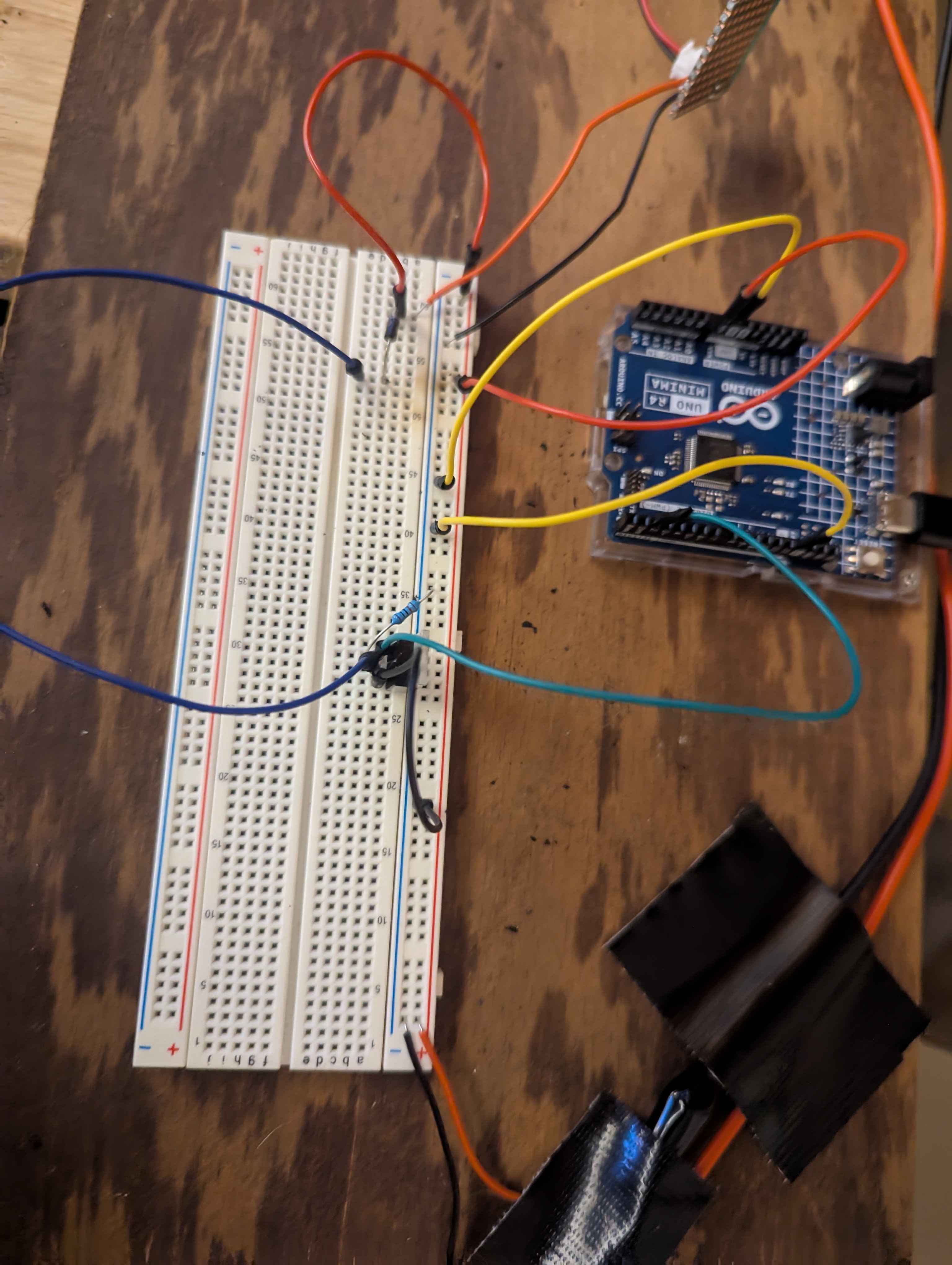
I'm hoping based off my pictures someone can spot what is wrong. I was running the board from usb, left that plugged in, turned on my benchtop power supply which as sending 12v to red, grounded is black rail on breadboard. I made one change in the photos...I disconnected one ground wire which was plugged in to the right side...other than that, everything is is exactly how it was setup when the error occured. Any ideas?
72 Replies
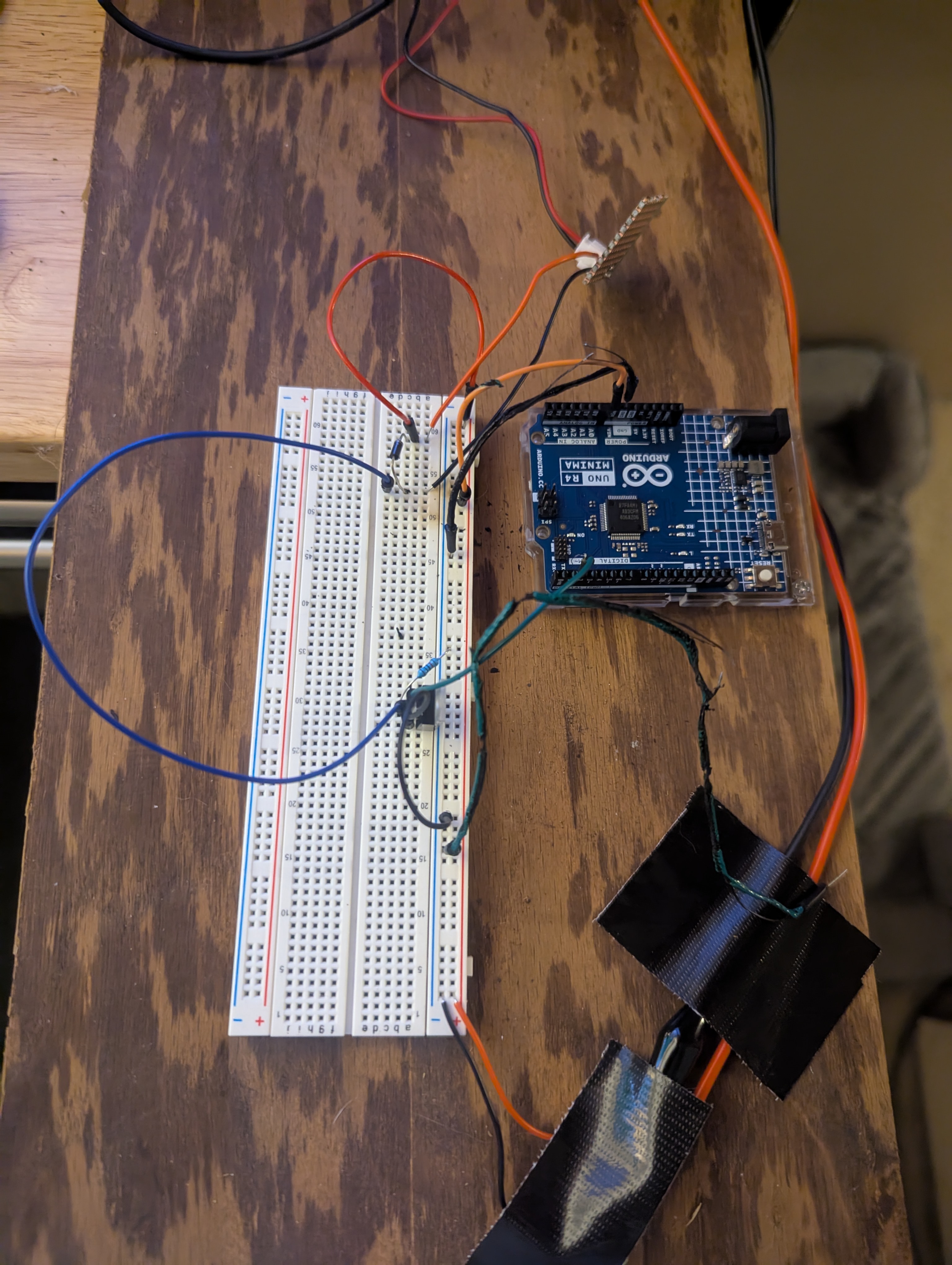
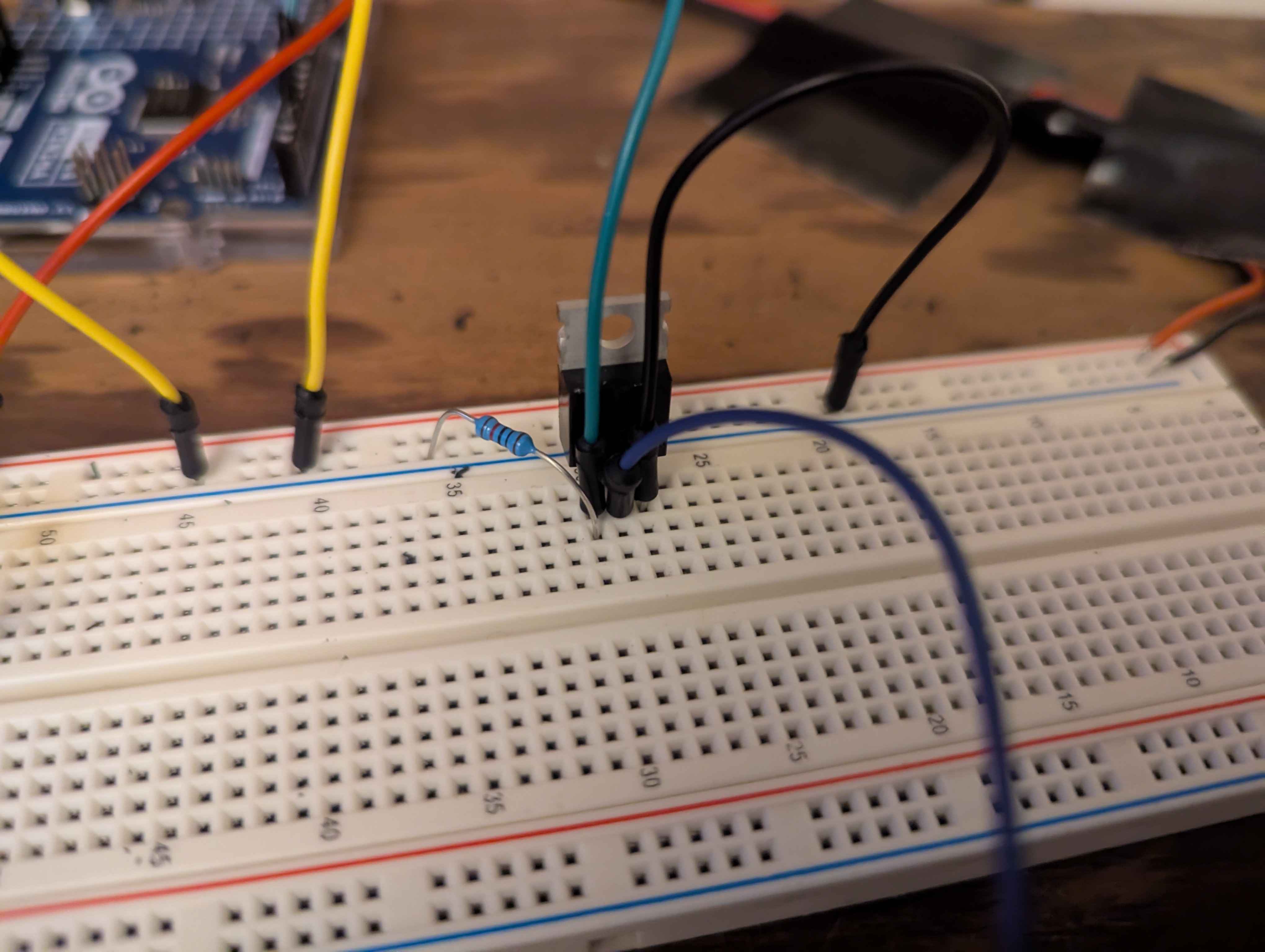
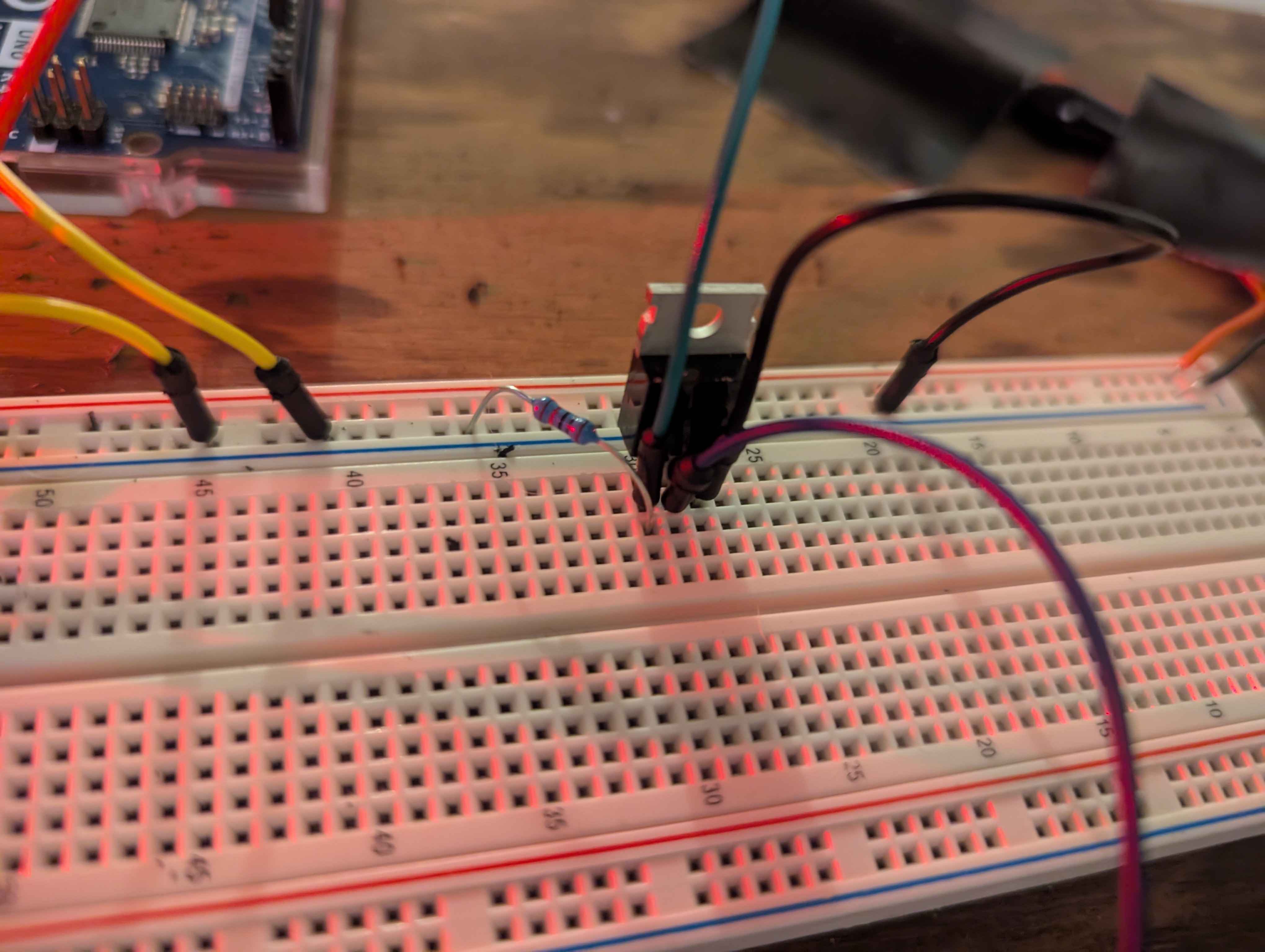
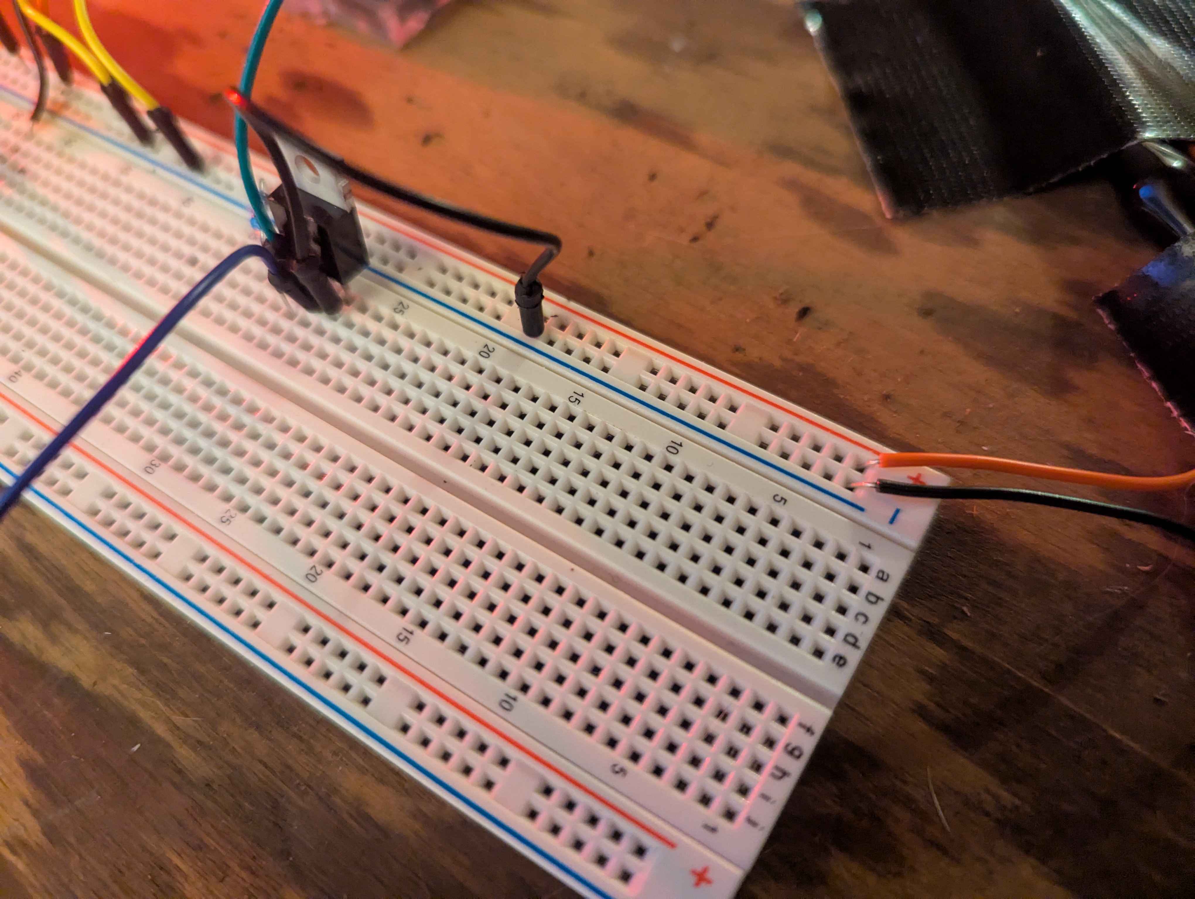
Another angle with both grounds gone :
it can be as simple as over loaded what is the fet driving?
to me it looks like you have a short through a diode? so IDK.
the fet is driving a UXCELL DC 12V 1.1A Electromagnetic Solenoid
so it shouldent had been an over load issue, so most likely a wiring issue, like the diode in backwords.
I thought the entire point of the mosfet was to not require the amp to go through the board /associated wires
I just went through it all again...turned on bench power supply and the wires started sizzling/smelling....I turned it off right away....not 100% sure what was going wrong but I assume it was the ground again
I just checked it all over again...everything looks perfect to me...
remove the diode and power it up
@hendr1x well?
@Maderdash : Sorry...juggling too many things
No wires melted...seloid was triggered right away (my code says wait a second).
so did you remove the diode?
yes...that was my test with the diode removed
Ok so most likely you have/had the diode connecteds as i said in the start. d b
do you understand?
Replace the diode with a new one, but this time put it in the opisit way of the way you had the old one, retest.
I don't understand. The diagram shows the silver strip on the power side and that is how I have it in this photo clearly.
Also...why is my selonoid triggering...thats not right...it is suppose to get a signal from that arduino to do so
right so you have wiringiues
I did as you stated and it had the exact same effect as when no diode was present
I don't understand what is happening. I don't know what wiringiues means
The schematic says to put the diode with the silver side on the power side
I don't understand why my selonoid is getting triggered
so you have a wiring issue for sure then
Make a wiringdiagram and make sure it represents the way your current wiringis, WITH the diode in place please.
Is this what you are asking for?
As far as I can tell that is exactly what I have setup...its the easiest schematic in the world and I still managed to mess it up horribly
well that wirings CORRECT, so there for I need one that is following YOUR wireingi
Ok I got you so lets do this.
FYI Im currently in voice chat if you wat to talk let me know
so remove the fet, from the circut, and take check the part number on the fet please.
so I just found out something
When I test the two selonoid wires, they are currently shorted/connected
maybe that how it is suppose to be
again let me know when you have the part number
Ok great
So the RIGHT pin or source is conected to what?
S is going to ground
OK now what is the next pin connected to
D = negative seloniod lead
positive selonid lead is coming back to power rail...there is a diode between them
Ok so the SORCE is contected to the negative side of the solinoide.
AND
The NEGITIVE side of the diode right?
It is now because you had me change it. However, as I read the schematic...it is showing the opposite
is the schematic wrong...or am I reading it wrong? That was a number one search result on google...very popular
Ok moment.
So the schematic HAS the negitive side of the diode contected to the sorce, so the schmatic is corect. the STRIPE is the positive side of the diode and in the diagram it is conected to the positive side of the solinoid .
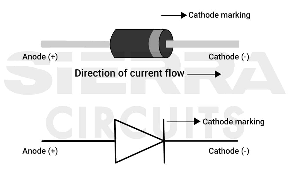
The silver strip is on the positive side in the schematic
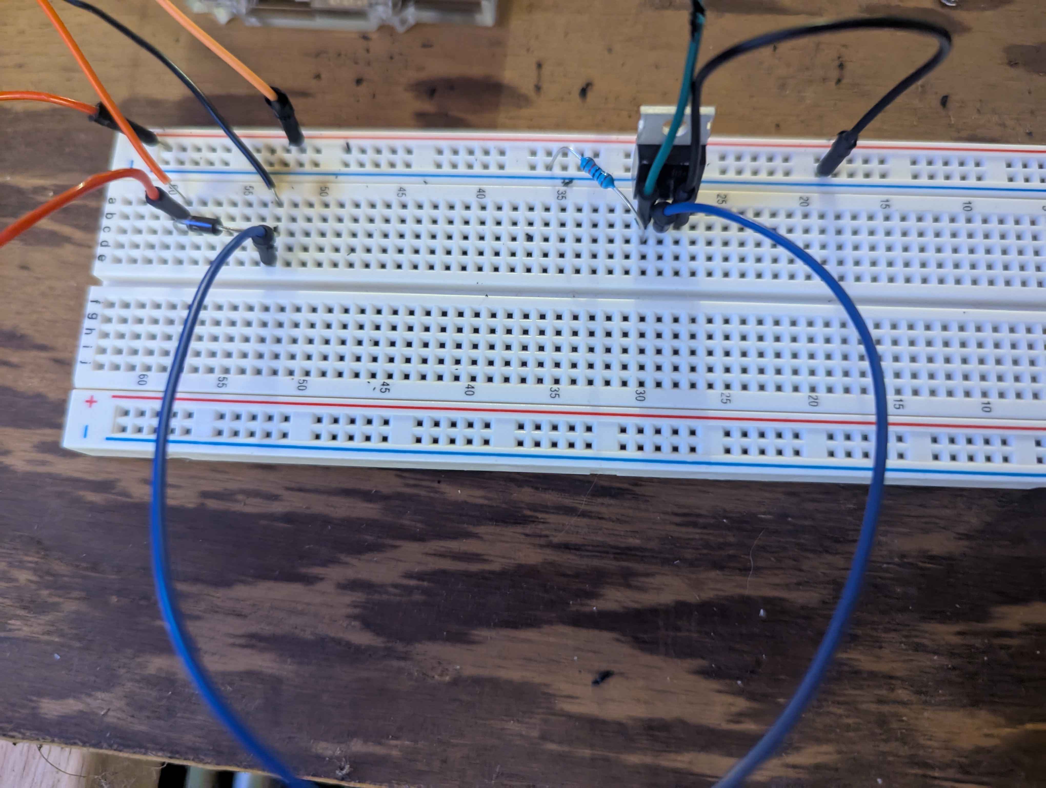
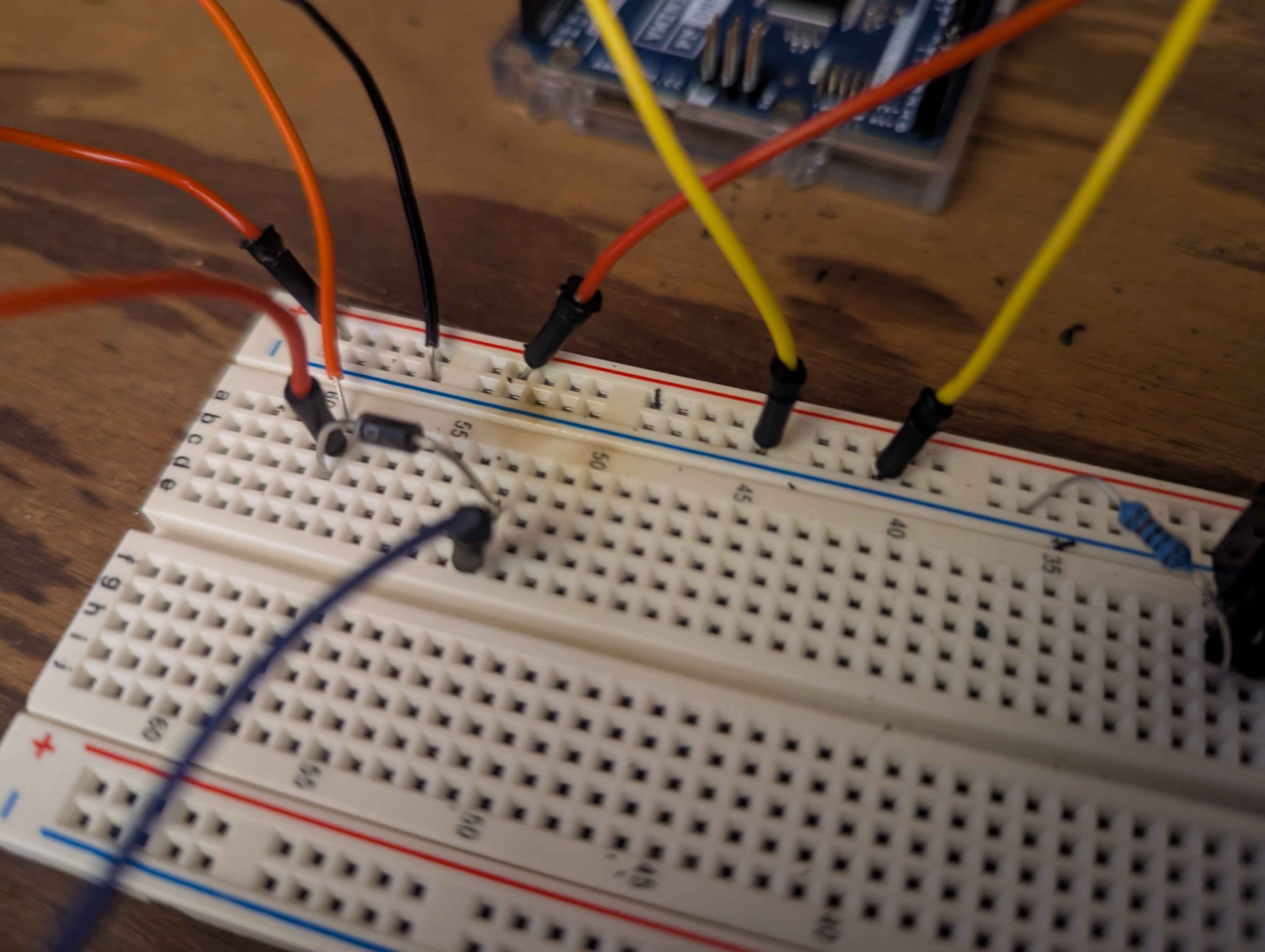
better image :
Correct, so the NOT striped side is now currently connected to the DRAIN.
NOW .
IF not then make it so NOW.
Ok...I have it as you described and how the image is
this is the configuration that causes wires to melt
OK now, the STRIPED side is connected to Positive of the POWER SORCE, not 5v on the Arduino but the actual POWER SORCE correct?
Correct
Great, NOW the Positive of the solenoid is connected POWER SORCE also. corect?
So, I'm using a bread board....in one row I have the diode cathoid side, the positive of the selonoid and the 12v positive from power supply
Next connectd of the POWER source to the ground of the Arduino please.
So I'm running eveything from a 12v bench power supply right now.....I'm using a uno R4.....power supply is running to the breadboard positive/negative rails...I have a power cable running to the VIN pin on the arduino and two ground wires running to each side of the arduino grnd pins
Ok then take a clear picture of this current ireing
So to be clear, on positive rail I have selenoid + arudino, on negative I have two grounds to board.
Lastly, on the G of the fet I have a wire going to pin2 on board and and 10k resistor to pull it down
I'm taking picture now
Ok cool
want me to test it real quick as well?
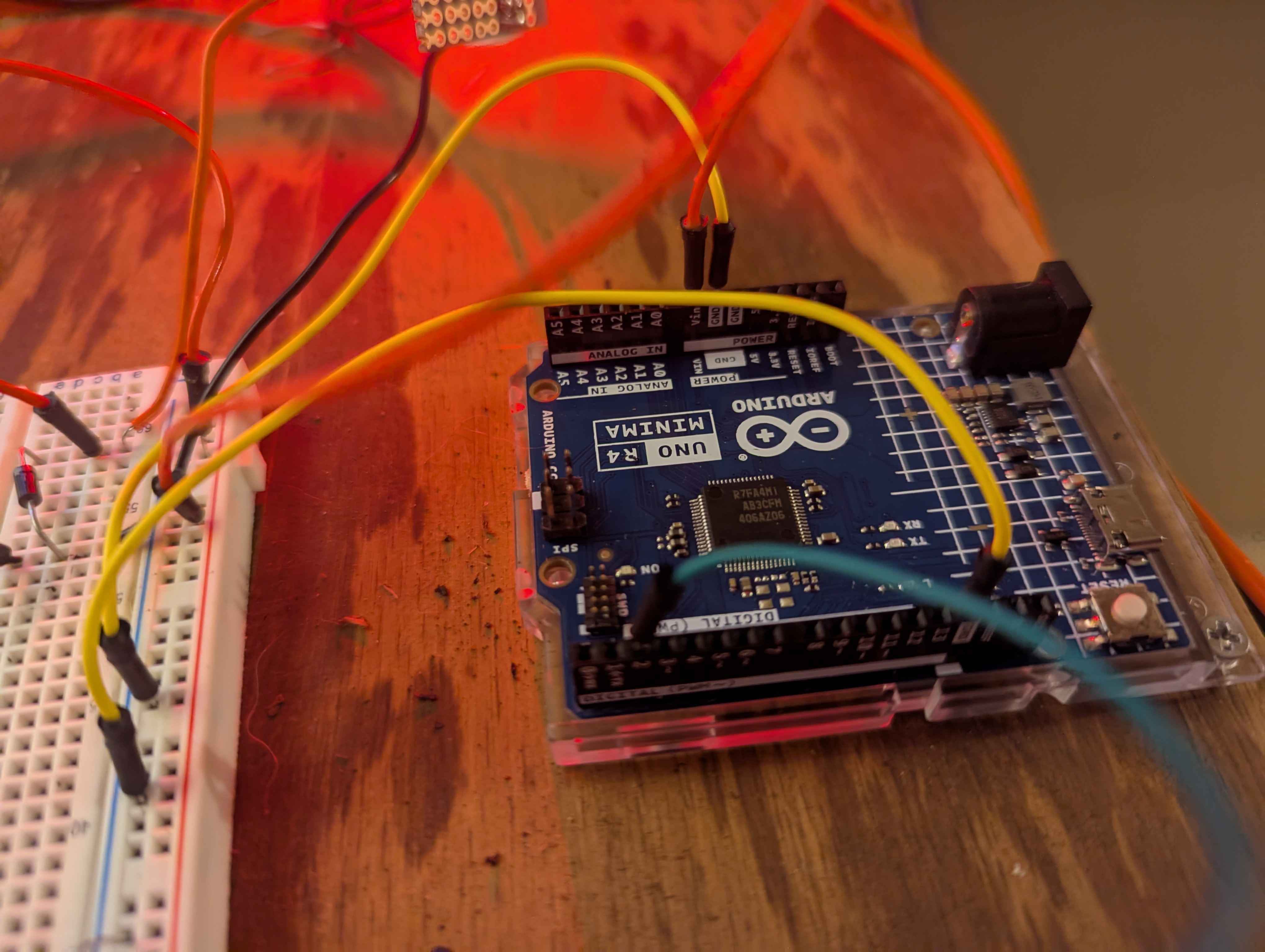
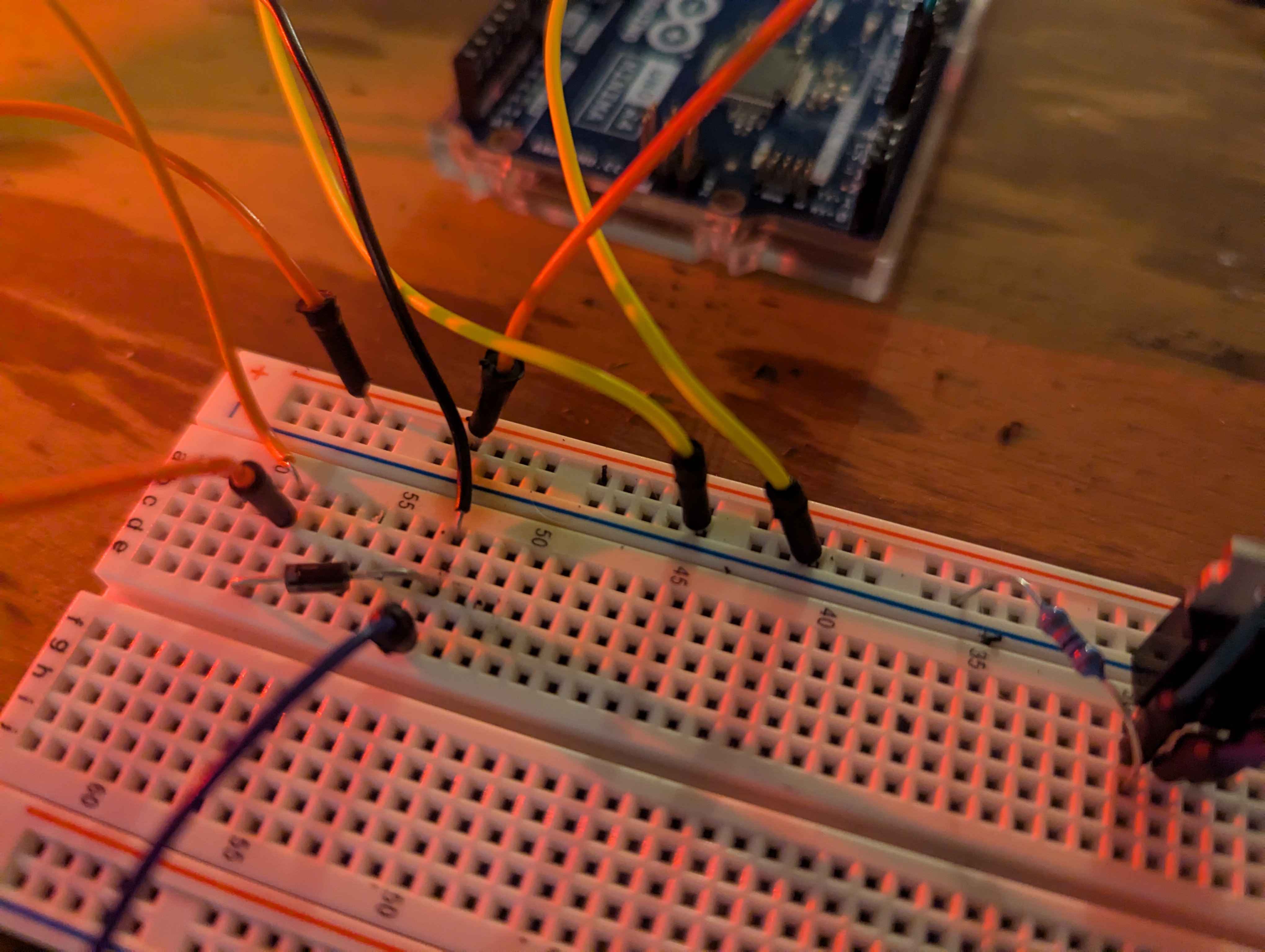
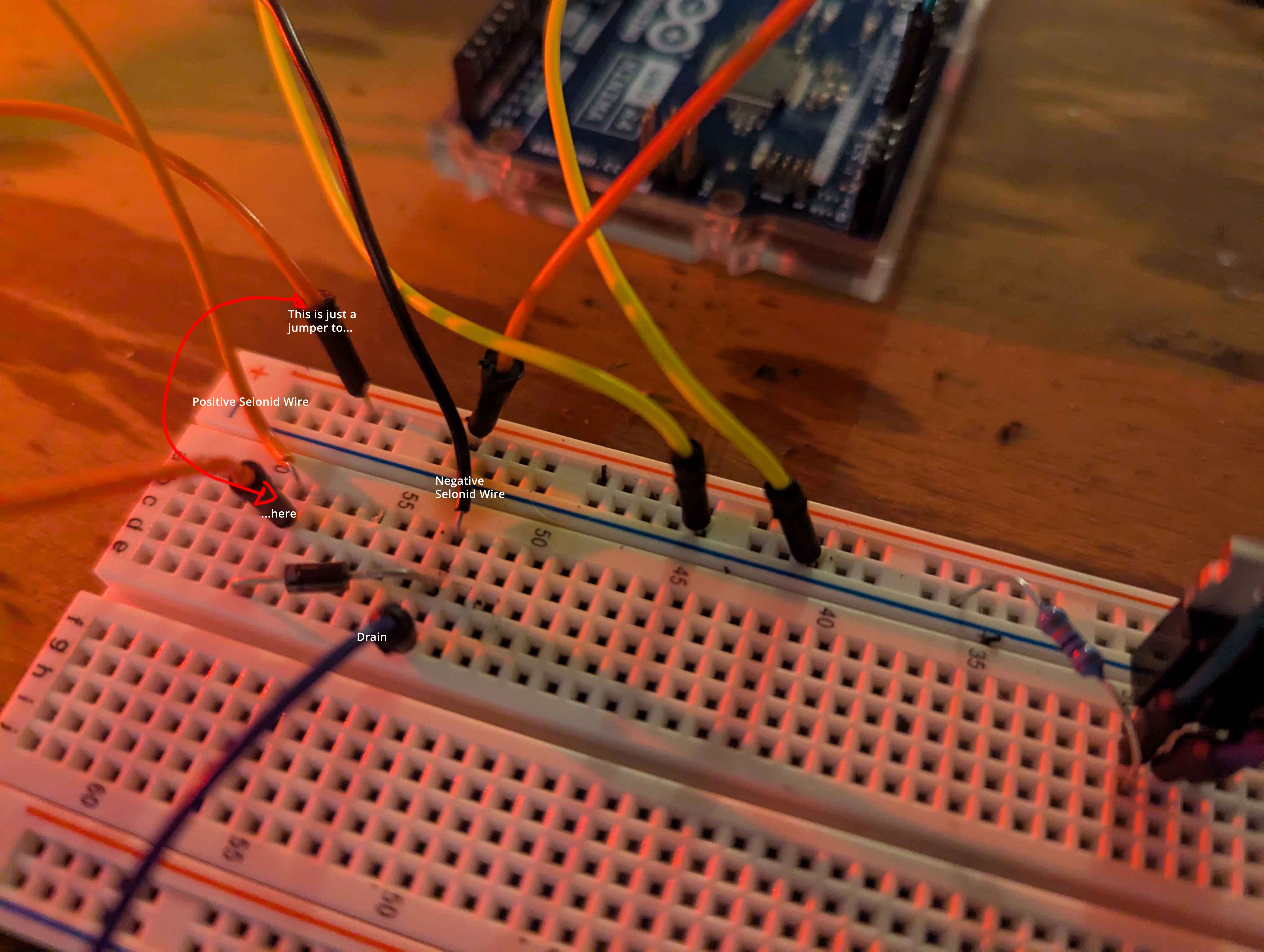
added some labels to help
moment looking
Ok do you have a multi meter.
Yes
Ok so lets do this.
Remove the fet leave everything else just the way it is please.
Now You should be able to power this up and NOTHING should burn, but be sure.
[I know nothing will work, but we are just going to take voltage mesurements]
So nothing burnt but my seloid did get actuated
and I don't want to leave that on..it will burn out I think
ok something is wired wrong then.
keep the fet out. and unhook a single wire from the solenoid, so it will NOT power, then try power it up again.
ok...I pulled out the ground...no fet...system powers up...no burning...no seloniod triggered
OK now take your meter, and test the rails.
shit
it says -12v
yep...I attached my power supply in reverse
RIGHT so all of your wiringas BACKWORDS.w
So fix that, then try with just the solenoidd,d
If it does not activate, then power down drop in the fet, and retry.
fixed..so reattach the solenoid?
ok...so reattached solenoid...power up...nothing happened, added back in diode...nothing happened
Yup just do the it in reverse.
Ok now add the FET?
done...powers up nothing happens
which I think is good
but I don't think my board is running for some reason
now your wiringshould be correct?
not sure if its fried
I believe so
well you could had killd it, OR it might NOW be wired wrong, so multi meter time again, and if you must unhook the board from the power supply and see if it will power up by usb.
the board works by usb
the selonid triggered after 1 second, for 1 second...as coded
so I would make SURE you have the wiringNOW correct to the board and the bread board.t t
confirmed positive/ground wires read 12v properly...when connected to board nothing happens
But I think you got it from here right?
So my board is dead right?
sounds like the VIN port is.
anyway to fix it?
I can research that on my own
thank you so much for your time
I really appreciate your help
I think the wiring is perfect now. I learned a good lesson!
Your very welcome. when you said the solenoid the fet REMOVED, thats what told me the power must be backwords, and then all of the rest of your issues made total sence. d