RP2350 based PCB review
I would be glad if you can review my RP2350 based PCB: https://github.com/semitov/rp2350-gpio-card
GitHub
GitHub - semitov/rp2350-gpio-card: Framework Expansion Card based o...
Framework Expansion Card based on RP2350 providing GPIO to the mainboard (OSHWA UID: IT000024) - semitov/rp2350-gpio-card

7 Replies
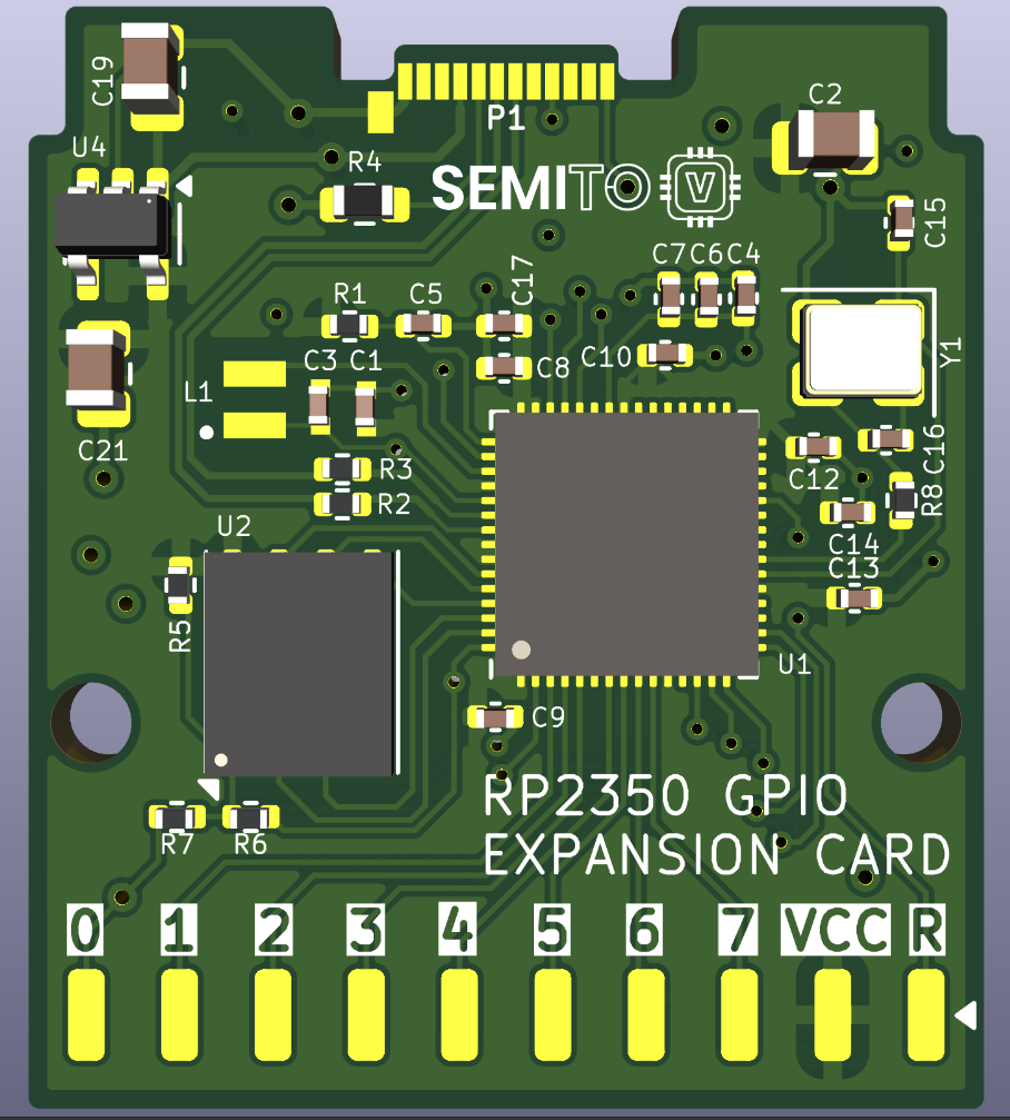
just from the 3d image alone i would say pay attention to capacitor placement as it doesnt seem that great
Yeah, thanks for comment. They should be more nearby to the chip. I also got some comments about impedance matching of usb lines. Here is the latest revision:
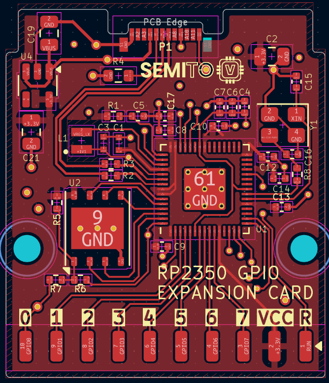
C2 is like general cap for 3V plane
Its still rather poor
USB impedance matching is nice to do but really wont make a difference here
u4 im guessing is transient suprresion for USB?
if thats the case its way too far away
P1 only has 1 structural pad on the left? not on the right as well?
It has another one mirrored behind, its the footprint of component
Its a pretty tight fit around U1 already 😅
Its 5v to 3.3v converter. AP2127K-3.3TRG1
But would decoupling caps being a bit far create that much of an issue? At the end this is a very tiny board
just makes them less usefull to even useless at times
doesnt matter for your functionality broadly speaking but its good to do and improves performance
I ordered it. I hope it will work. 😅