31 Replies
I recommend checking if the solder is good. If you have the budget, maybe buy an esp32, and check if you can find the driver in the webpage where you bought the lcd from
The TFT on wokwi is different from the 1.77 tft Graphite is using. I made a counter to display in the loop section, and it's upside down and backwards but it works.
I gtg in an few mins
@Graphite if you have time, @Fireguy9143 might have found an solution for you
The thing is, the code works in like the first second. So it might be a clock error, or communication SPI/I2c error. The wrong pins might be used, the arduino might be fried, or the wrong or corrupted driver might have been used
@Graphite please share the place you got this screen for (the link)
I gotta go
If the display works on reset, it means the driver is working even if it "shouldn't". This seems like it must be a problem executing the code. I think it would be good to check the loop and see if it runs, and check the voltages on the pins.
Is this an hardware or software problem?
If it’s code , then I think the next strip should be completely clearing the clash like I shared earlier
*flash not clash
1. Open avrdude Folder
Go to:
C:\Program Files (x86)\Arduino\hardware\tools\avr\bin
This folder contains avrdude.exe.
⸻
2. Open Command Prompt in that Folder
• Hold Shift + Right-Click inside the folder.
• Select Open PowerShell window here (or Command Prompt).
⸻
3. Run Erase Command
Replace COM3 with your Arduino’s port:
.\avrdude -c arduino -p atmega328p -P COM3 -b 115200 -e
This erases the entire flash memory, including the bootloader.
^ to clear flash, but you would have to completely install the uploader which idk how to do
i would play with the bootloader as an absolute last resort
if you can upload and run Blink the bootloader is OK
what is this all about?
This is @Graphite s problem and he’s sleeping rn
Wait that’s prob the problem
And an cooked board
@AnonEngineering

Maybe found a major disconnect.
In the wokwi there is only the larger TFT, and it has:
1 VCC => 5v
2 GND => virtual Nano GND
3 CS => Chip select virtual pin 10
4 RST => RESET virtual pin 8
5 D/C =>DATA/COMMAND virtual pin 9
6 MOSI =>Master out/Slave In virtual pin 11
7 SCK =>Serial Clock virtual pin 13
8 LED => 3.3V
9 MISO (which I didn't use)
And the above setup worked with the code as it was written/provided...
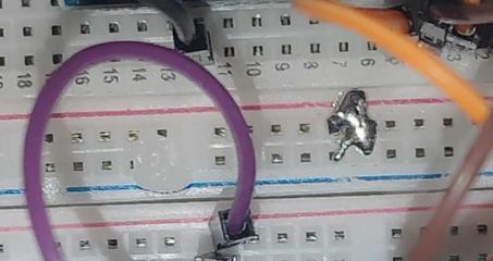
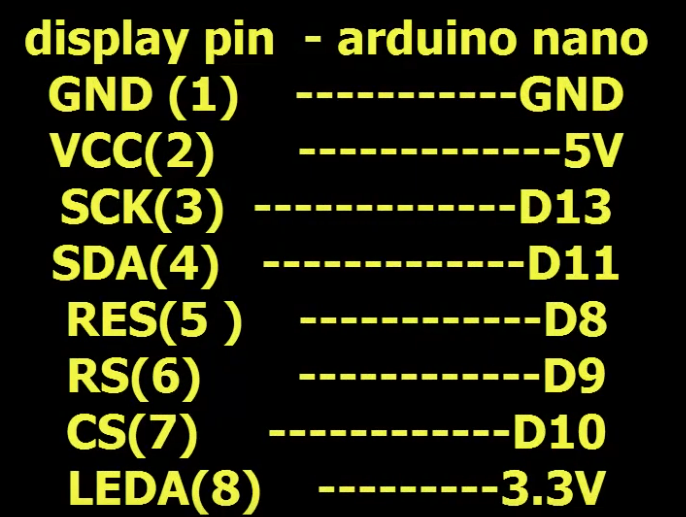
On the pic that Graphite sent, it has:
1 GND => Nano GND
2 VCC => 5V
3 SCK => PIN D8 (Maybe should be A5?)
4 SDA => PIN D12? (Maybe should be A4?)
5 RES =>RESET PIN 13? (Maybe should not be the MOSI variable in the code?)
6 RS =>Data/Command PIN 9?
7 CS => CHIP SELECT PIN 10?
8 LEDA =>3.3V?
9 LEDA
10 GT_CS
11 GT_SI
12 GT_SO
13 GT_SCL
14 GND
It looks like maybe your TFT is mixing up the clock and reset pins?
the story continues, it's going to turn out to be one or more of the above issues 🙂
Well, it's been an interesting puzzle. I hope we hear back on what's what.
It’s very interesting…
The OP "confirmed" the wiring.
Yeah, I know. My chart is best guess from the overlapping wires
Is it hardware or software?
my bet is wiring of some sort
K
OP has tried multiple different codes
that whole reset business is suspect
It’s probably an Brocken clock or bad clock
Or bad comms
With spi/i2c
Clear pics of wirring and an explanation to this could help
🤣
I do not believe the OP removed the wires and redid them as requested.
the space/time between request and confirmation was too short, resulting in a reset of beliefs, from a watchdog timer
True
He needs to remove the soldered jumper shorting the +-
there isnt anything on that rail
That jumper is just an ticking time bom*
For future projects he might forget
Dont be so short.
(joke)
(I am short)
I’m 5 2
(To be fair I’m 13)
:uno:
I SOLVED IT
IM SO DUMB DUDE
I JUST HAD TO BRING THE LOGIC PINS DOWN TO 3V3
I DIDN'T DO THAT APPARENTLY???
I WAS CONVINCED I DID
Even tho i figured it myself, you were a huge help dude! Kudos for knowing so much about this stuff at 13
I started programming around that age but working with electronics is a whole another beast
Thank you everyone for the ideas, im js glad to be done w this bs
👍
:puppet_4:
Esp 32 does that automatically jk
Your welcome
another case where having level shifters on hand would have helped 😉
the pots that I think @DarwinWasWrong said earlier would also have worked