DIY Halloween Project Help Needed
Hello, all this is my first post in discord, although a long time arduino tinkerer. I am absolutely stumped why my project is not working correctly.
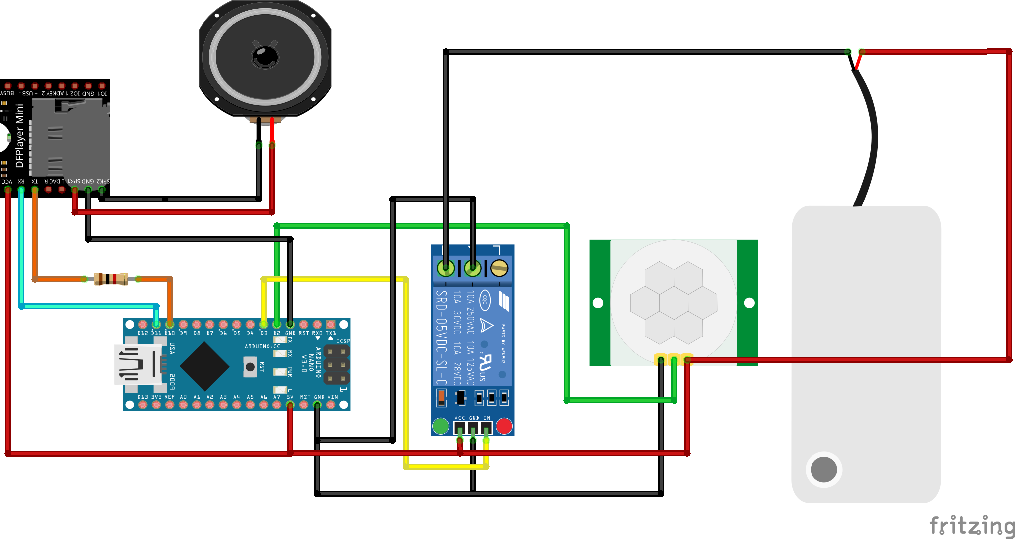
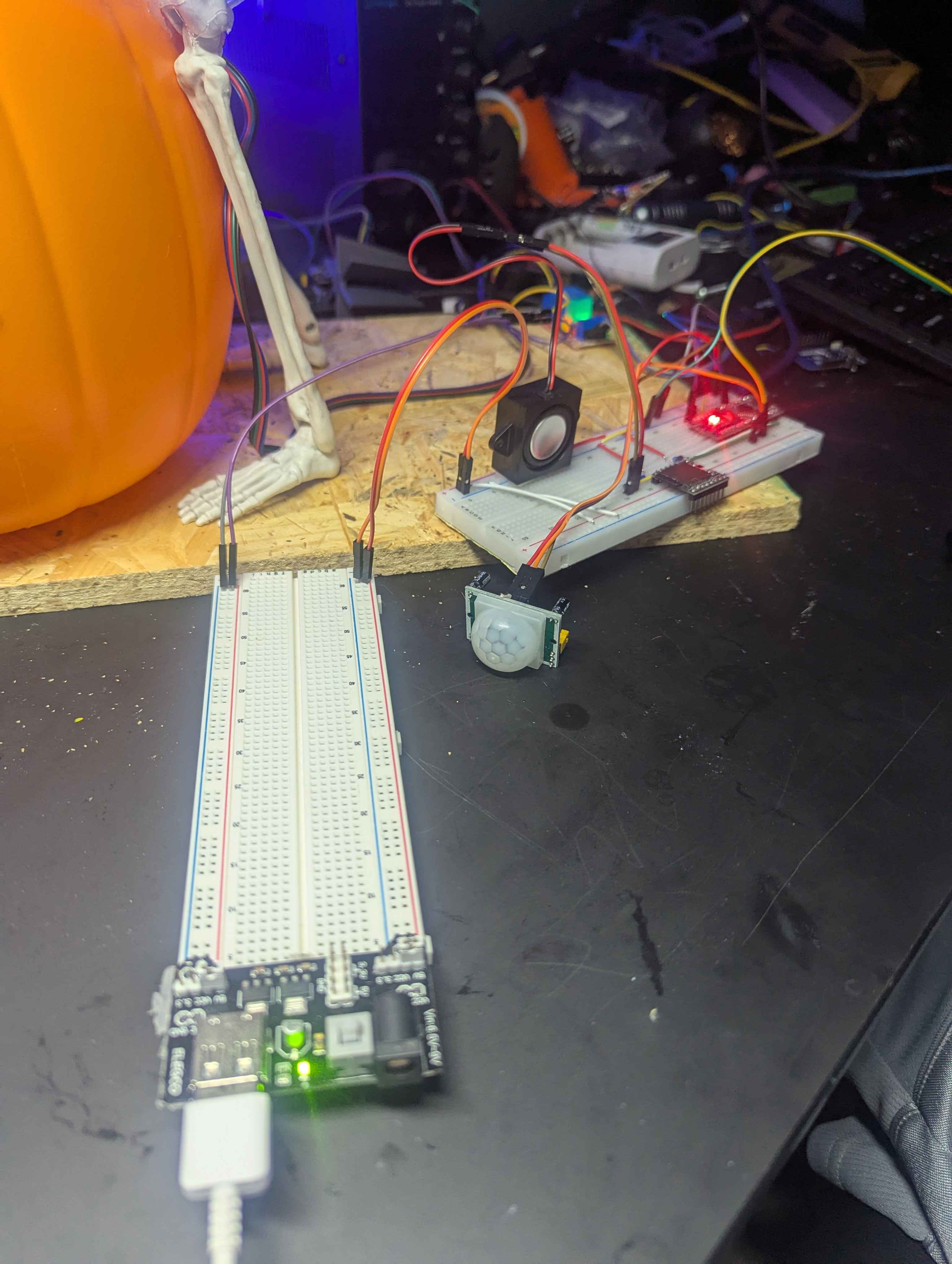
Hardware:
- HC-Sr501 PIR Sensor
- 5v Relay
- DFPlayerMini & Speaker
- Mega, Nano & Esp32 (I tried with all of these not at the same time obviously)
How code should run: Pump is connected to NC so always running , when motion detected on PIR, relay pin goes high stopping pump, DFplayermini plays a random sound track, waits 5 secs to let sound play, then pump goes low and resumes pumping.
Issue: When I have the pump fully connected to power, the PIR is just constantly triggering. if I remove the power to the pump, the code and relay trigger as intended. I have the PIR time delay pot set to about a 30sec delay. I have tried using an external 5v power supply thinking the small pump might be pulling more than the board can provide. When using the esp32 I have a development board that has a dedicated 5v output thats what i connected the pump to. I am just absolutely stumped, beating my head for about 2 days on this, which I thought would be rather quick and simple, has really stumped me. I was also unure how to uplaod the code so I uploaded a txt file as well as here https://codefile.io/f/SEoBQW4V6B, both esp32 and nano code are there.
Thanks in Advance for any help or suggestions.
33 Replies
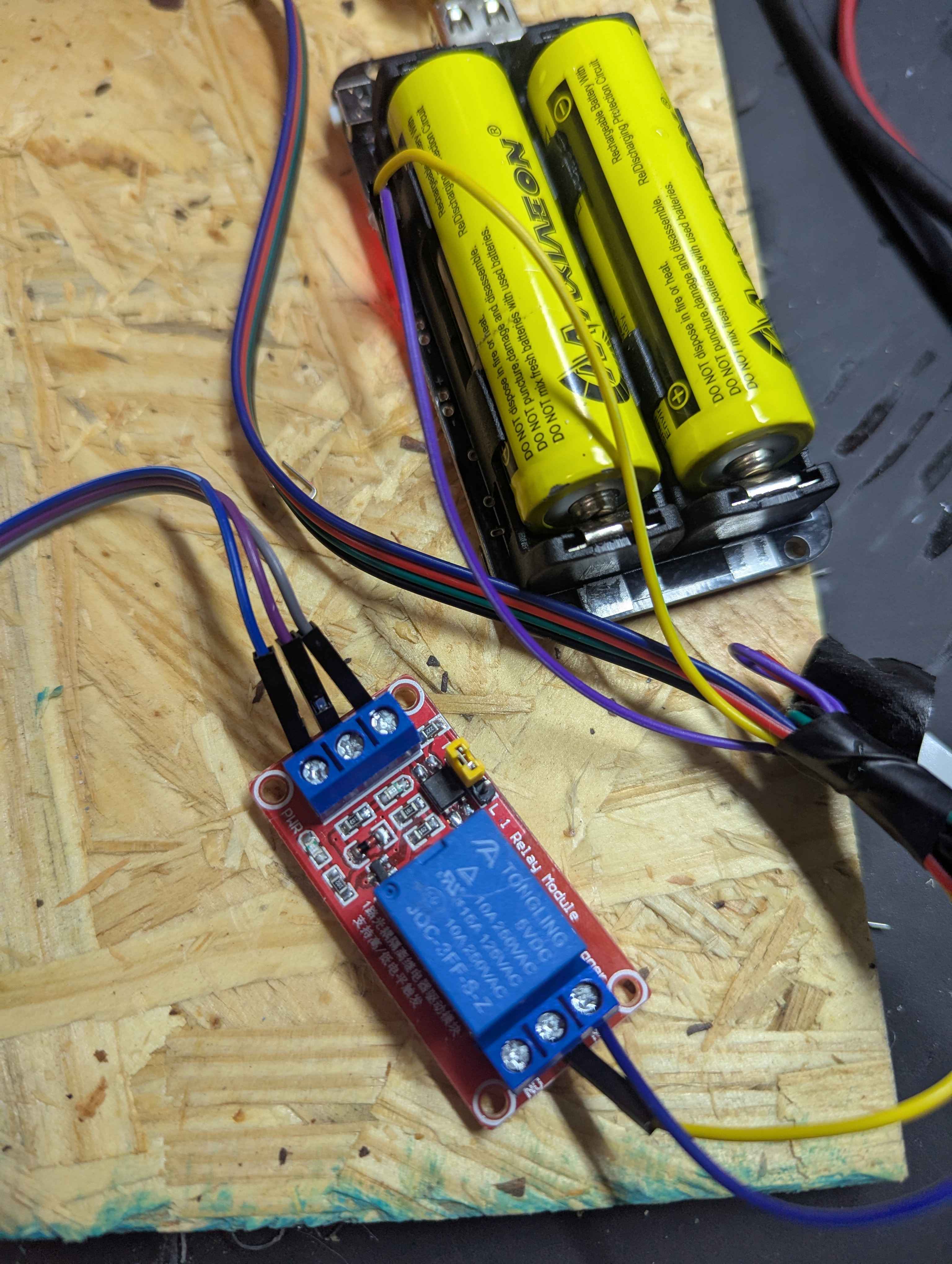
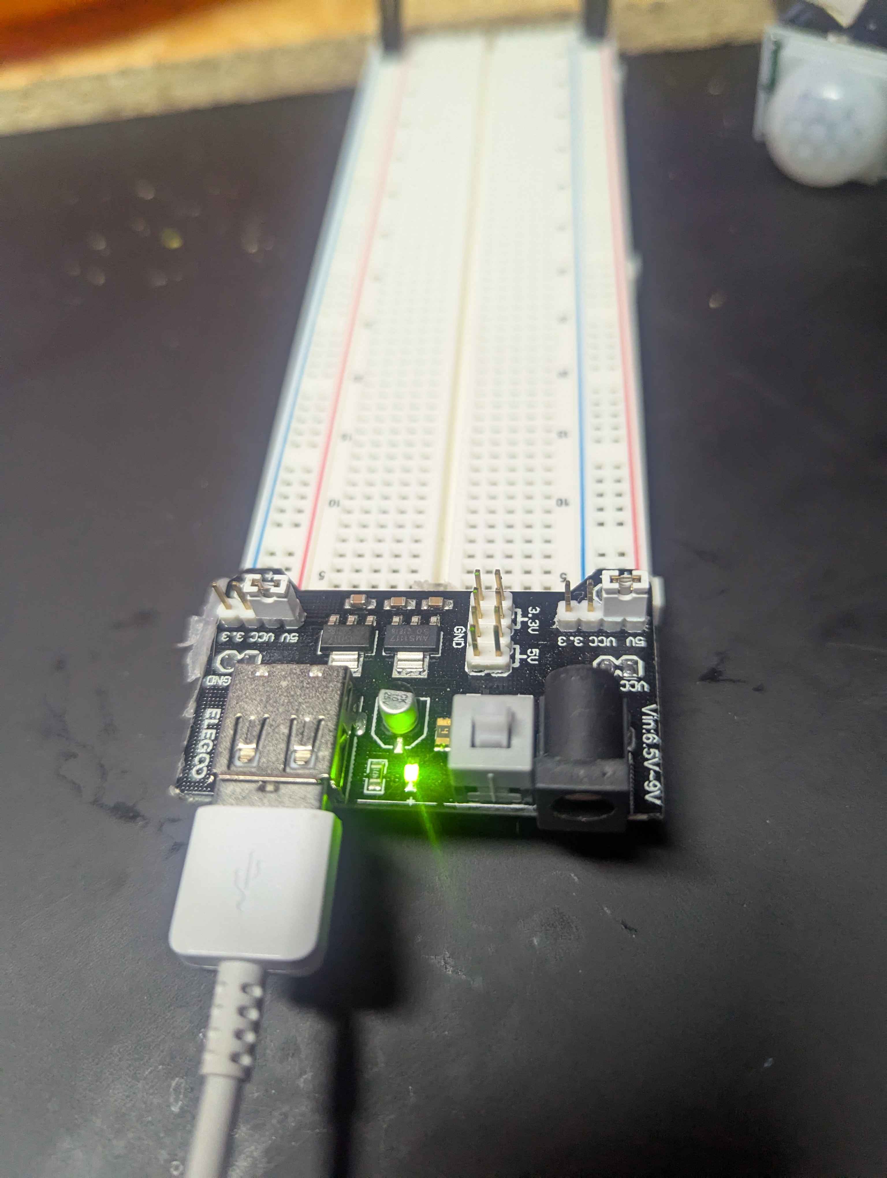
First thing I'd try is using a 4xAA battery pack for the pump and completely isolate it's electrical noise from the system. As shown it is running off the logic 5v power.
the small motors on those pumps are very noisy, if isolated power doesn't work you could try some 100nF caps right on the motor to bypass the noise
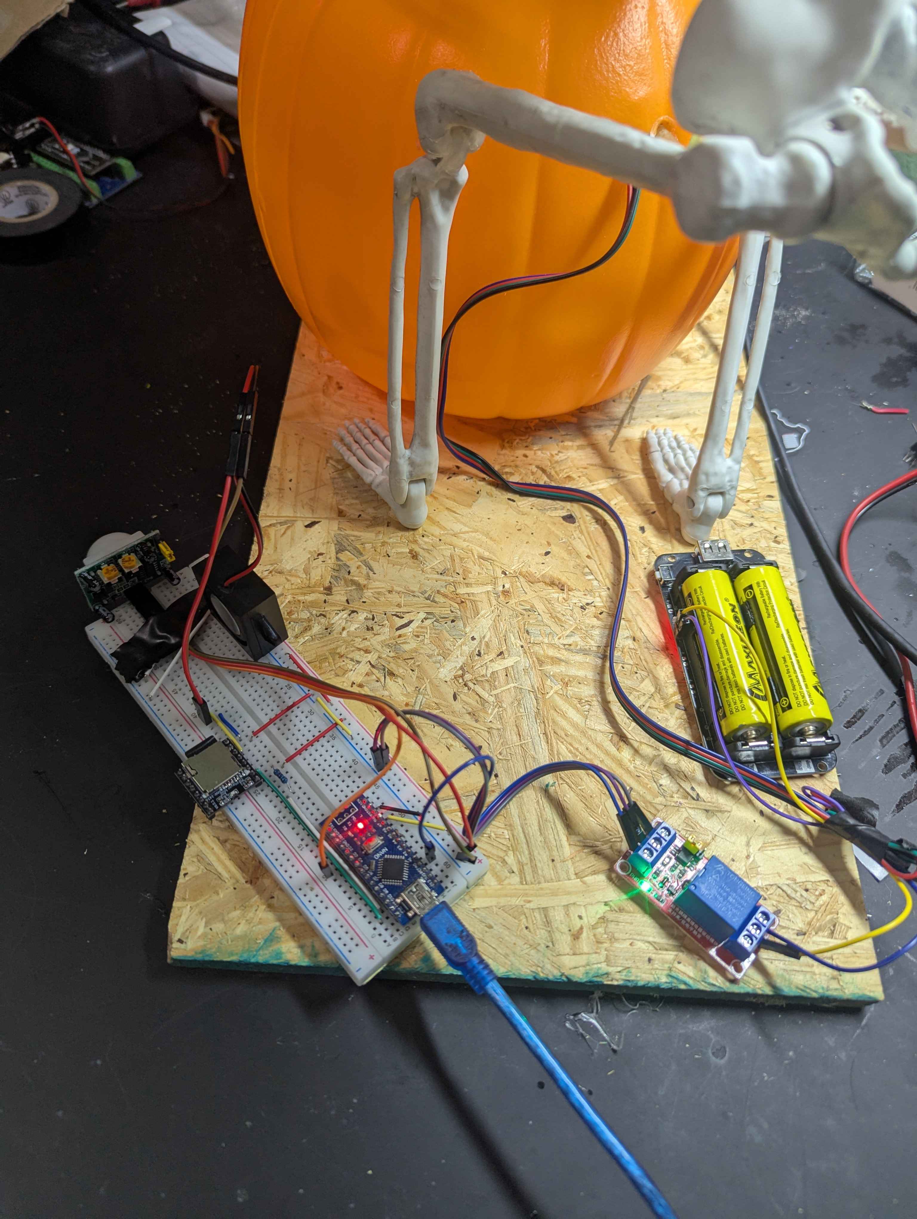
Ok I didn't have a AA pack but I had a 18650 pack that puts out 5v. And I'm still have the same problem, and sorta. I have the relay side which has DC+ ,DC- , IN. Which are in 5v , GND and the control pin. I moved and simplified the the components to a breadboard , and tried to separate the relay and motor wires away from the project. Now it seems that the df player won't boot when the relay DC+,DC- are plugged into the breadboard. But if I leave them in plugged let the Arduino boot then plug them in I can get it to run from what it seems ok.
you have your
SoftwareSerial pins configured correctly?
it doesn't make much sense that connecting the relay module Vcc, ground, and IN pins have any effect on bootingYea DFplayerworks great when realy isnt connected. At the moment I have hacked it working, I have taken the DC+ from the realy and put it in A2(pin 16) , after the DFplayer intializes I then set that pin to high, relay is powered , and from there it seems fine. But if i have the relay plugged into 5v on the arduino issues arise. And I agree I have no idea why its happening, makes zero sense I am going to swap the relay but i highly doubt its a bad relay its technically fuctioning correctly.
do you have a multimeter?
it makes no sense that a HIGH from a pin is fine but HIGH from 5v is not
I do what can i test, not sure what I am looking for
is your 5v power rail really 5v?
and - if you disconnect the pump from the relay does it still screw up?
5v rail reading 4.662v
a little low, but acceptable
taht is from the pc usb but i have tried froma good 5v power source , I will actually switch to that now.
the "5v" pin on the Nano is one diode drop down from the USB voltage, so 4.7v is OK
removing the pump does not have any effect
🤔
so it's not motor noise...
if you pull the 5v wire to DF Mini, wire everything back, then plug in the Mini after everything powers up does that work?
ok dude I swear all I did was move teh relay DC+ back to 5v and its working. LMAO kill me now cause i have no idea what the issue is. I am still testing rebooting a few times. but DF seems to be booting
sounds like a flakey wire somewhere, those dupont cables can go high resistance
i would not power the relay thru a pin
yea i try to use proto board cause these duponts suck. Oh trust me I would not either, I know thats not a thing to do. I still ultimately want to have like a single 5v power supply powering the whole thing.
is there a way I can use a single power supply, but keep the power to the motor isolated. diodes?
Ill keep updated if i get the 5v psu wokring. Thanks for yout help. very much appreciated
yes, if the supply can handle the current and you have adequate bypass capacitors (adequate = whatever it takes 🙂 )
Ok it's definitely power related. I tried this bread board power and the old issue of constant trigger returned. Ahhh. Lol two steps forward and one step back
those breadboard power supplies can't deliver much power, how much power can you squeeze outta this little guy?
i would think that USB power bank thing would do the job...
I don't know if I feel comfortable putting that outside. Also was gonna have it on a smart switch . I am gonna try today with a 5v like 2amp barrel charger if needed I can run one for pump and one for Arduino, given it wants to cooperate
Dude, how does this even make sense, completely isolated PSU for motor, as a sanity check I double checked my relay was good. As soon as I plug the battery pack in constant triggers. It's absolutely boggling my mind.
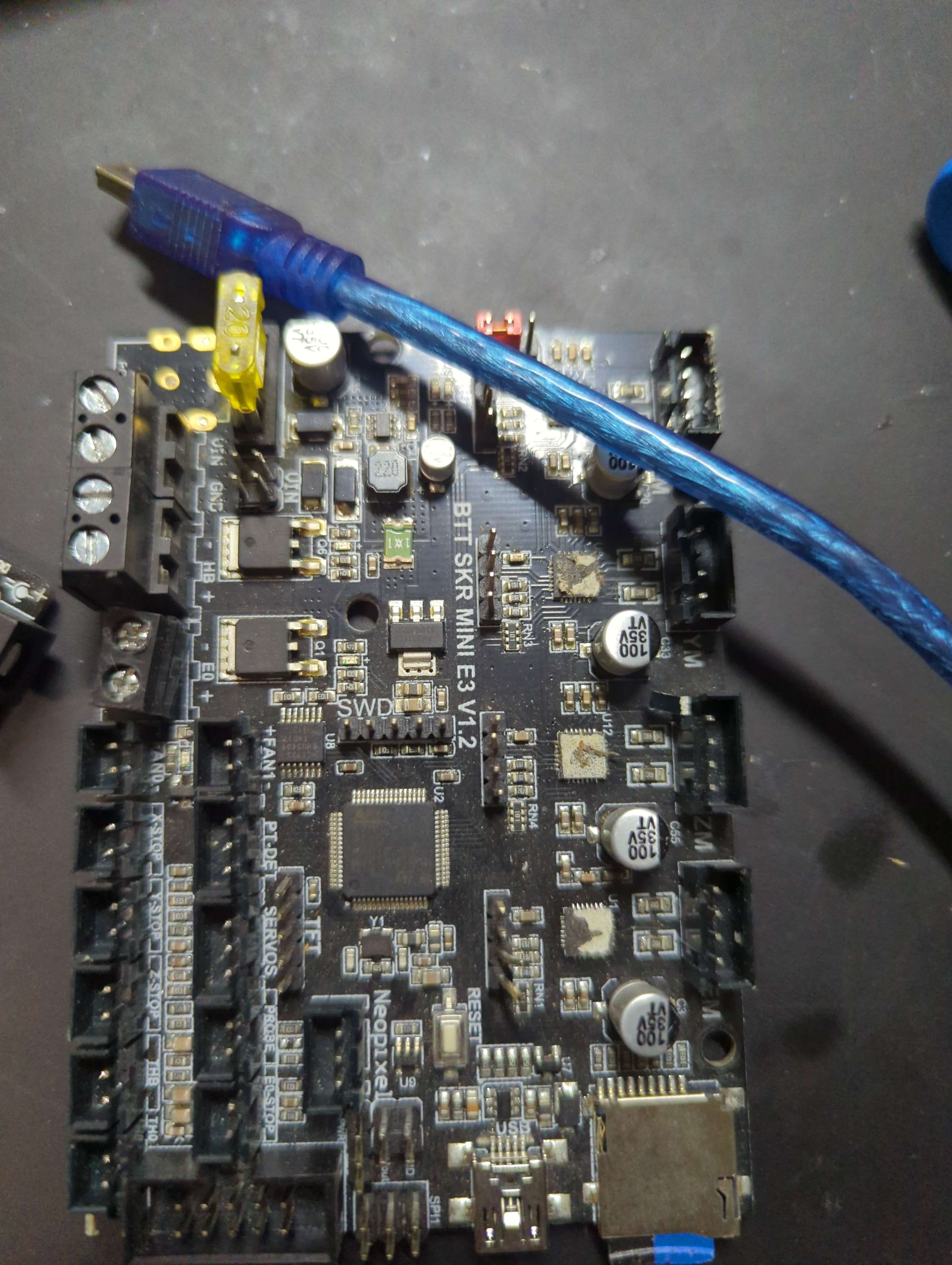
I might try to use this old 3d printer main board
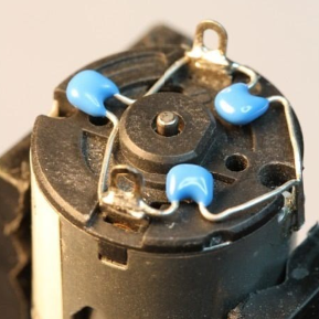
try the bypass caps on the motor
Can you give me a brief explanation on what to do. Is it just a cap on one side and then two on the other but gnd in-between
to be effective you want them right on the motor
https://discordapp.com/channels/420594746990526466/1420420886095200326/1420434023754236029
otherwise your wires act as antennas, radiating noise
so take the pump apart? I don t mind I have a few if i break it, its ok.
yes if you can, those look glued together
maybe try a 100uF and a 100nF in parallel across the relay terminals to start, not as effective but easier. mind the polarity on the electrolytic.
the point is electronic noise is being generated and received
your mission is to kill it at the source and mitigate it at the receiver, without an oscilloscope there is some magic involved 😉
i have an oscilloscope, just barely know how to use it lol
but ill try that today im also gonna make a little proto board instead of the bread board.
After everything I broke out my oscilloscope, and just started monitoring things when things went high and low, when I plugged in the relay. When testing the pit sensor I was getting crazy readings. I decided to swap out the pit for another and like that everything worked. I believe I may have fried the pir or something.