ATtiny85 hardware watchdog
Hi,
I have a Arduino MKR 1500 and a ATtiny85 that has to function as a watchdog for my arduino. There is a relais module attached to the Tiny. The tiny will send a HIGH signal to the relais when there is no heartbeat from the arduino. I tested with a voltmeter and the arduino sends 3.7V when its alive and 0.0V when its not connected to the cloud. However, the Tiny wont switch the relais when the arduino goes offline. I tested the tiny and relais with a simple sketch and that worked, so the hardware works. Anyone an idea why the Tiny doesn’t react on the signal from the arduino?
Tiny code:
const int heartbeatPin = 2; // PB2
const int relayPin = 1; // PB1
const unsigned long timeout = 5000; // 5 s voor test
const unsigned long resetDelay = 3000; // 3 s spanningsloos
unsigned long lastPulse;
bool inReset = false;
unsigned long resetStart;
void setup() {
pinMode(heartbeatPin, INPUT);
pinMode(relayPin, OUTPUT);
digitalWrite(relayPin, LOW); // start: voeding aan
lastPulse = millis();
}
void loop() {
bool heartbeat = digitalRead(heartbeatPin) == HIGH;
if (heartbeat) {
lastPulse = millis(); // heartbeat aanwezig → timer reset
if (!inReset) digitalWrite(relayPin, LOW); // voeding aan
}
if (!heartbeat && !inReset && (millis() - lastPulse >= timeout)) {
// Start power-cycle
digitalWrite(relayPin, HIGH); // spanningsloos
inReset = true;
resetStart = millis();
}
// Check of resetDelay voorbij is
if (inReset && (millis() - resetStart >= resetDelay)) {
digitalWrite(relayPin, LOW); // voeding weer aan
inReset = false;
lastPulse = millis(); // reset timer voor volgende cycle
}
}
Hope someone got any clue.
Regards
12 Replies
Pins and code looks good, according to https://github.com/SpenceKonde/ATTinyCore/blob/1.5.2/avr/variants/tinyX5/pins_arduino.h#L157-L164.
What voltage is the ATTiny85 running at? 5V?
How do you ensure heartbeatPin goes LOW when nothing is driving it? A pulldown resistor?
Running on 5v. Used a 10k pull down resistor between GND and PB2.
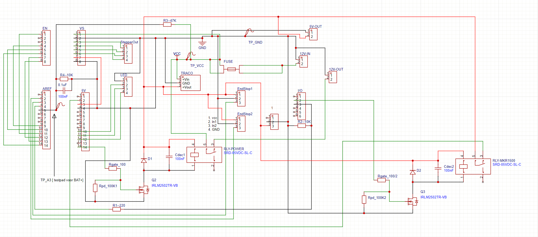
Do you have a wiring diagram of the system?
What do you want to know? Because I made the pcb by myself. They share the GND. 5v on tiny and mkr. Arduino A@ to pb2 of the tiny. 10k pulldown from pb2 to GND
number 4 is from my arduino "heartbeat" > 220 ohm inline > 10K pulldown to PB2 (no.3 on I/O)
mhm. maybe run a sketch that mirrors the input signal onto another output pin to check if it arrives correctly?
@Highfield
Tag Sent
See <#451158319361556491>
Arduino Bot • Submit bugs on GitHub!
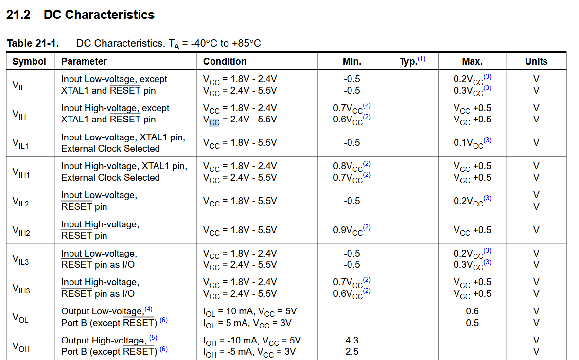
When VCC of the ATTiny85 is 5V, then the minimum voltage so that an input pin reads HIGH is 0.6 * VCC
which is 3.0V, so theoretically 3.6v should be enough
I was thinking about that, but I thought 3.7v was surely enough to see it as high
but that's something you can also find out if you run that mirroring sketch
Gonna try that when I'm back at my project! Thanks. Will be continued.
Got nothing on mirror pin. Put a level shifter between en it works. So definitely need a level shifter. Thanks for the help guys