
Official Arduino Discord - Discuss all things Arduino!
38,536Members
View on DiscordResources
Recent Announcements
Similar Threads
Was this page helpful?
 AAAA
AAAA AAA
AAA AAAA
AAAA AA
AA AAAAAAAAA
 AA
AA AAAAAAAA
 A
A AAAAAA
 AA
AA A
A AAAA
AAAA AA
AA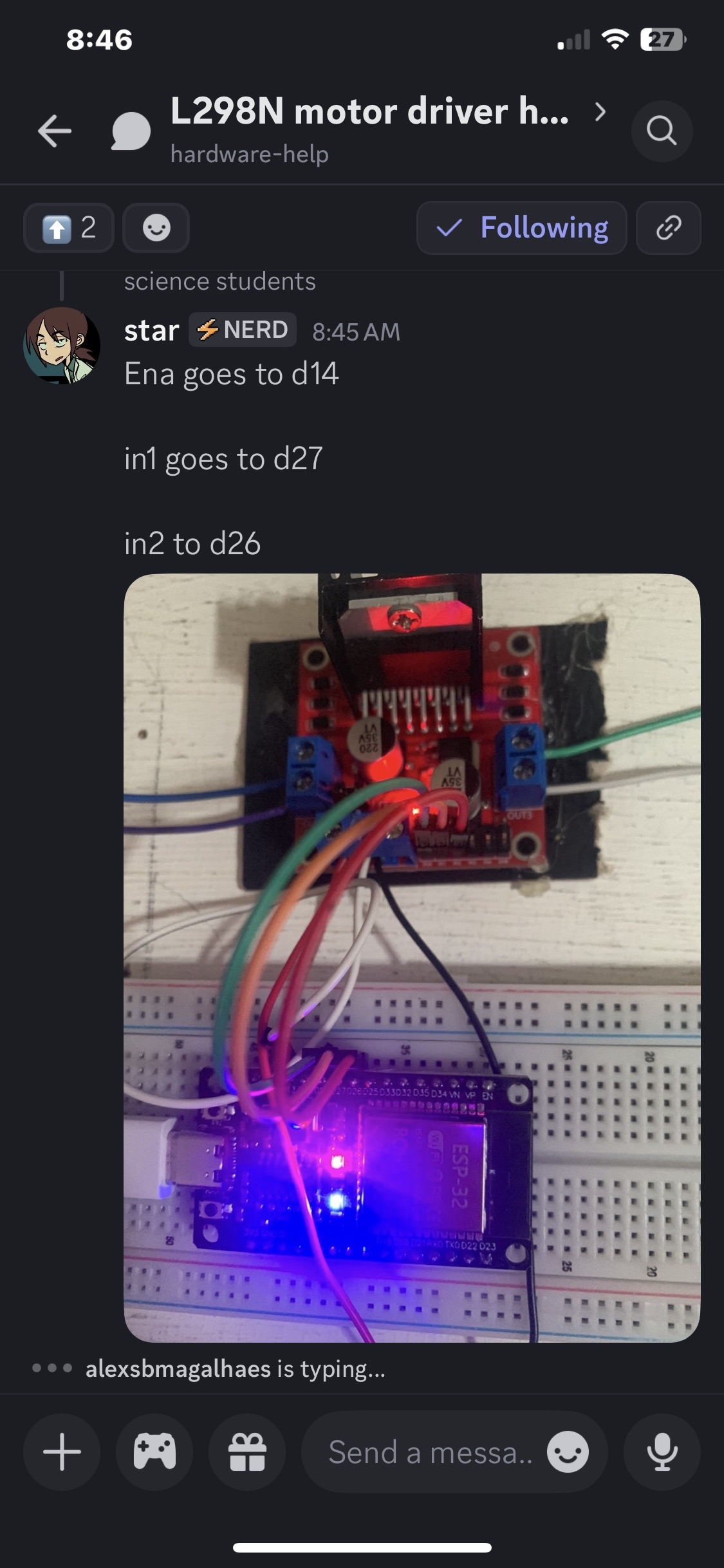
 A
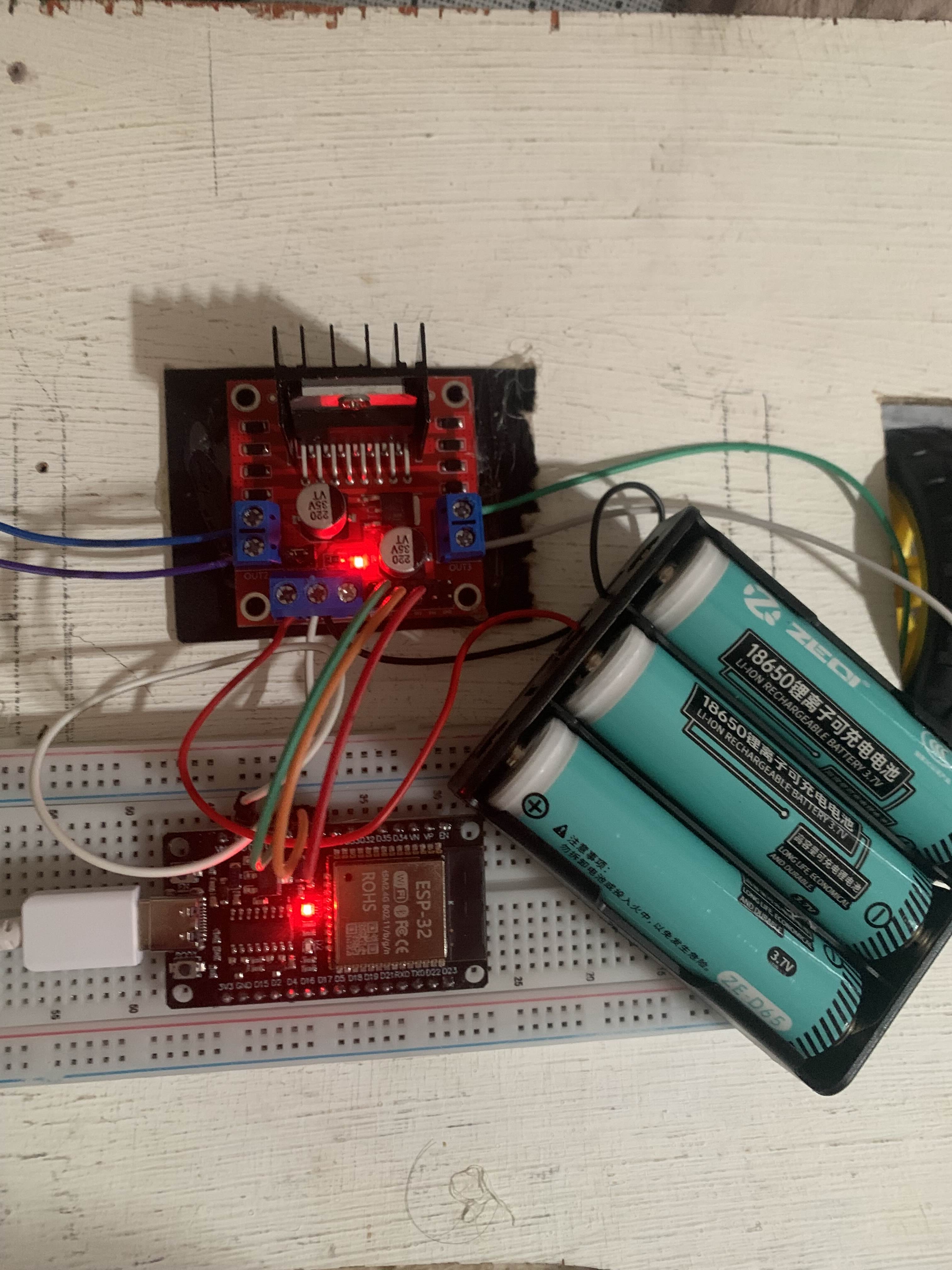
Aint motorone = 27;
int motortwo = 26;
int enable = 14;
int ledone = 2;
int DELAYone = 200;
void setup() {
pinMode(motorone, OUTPUT);
pinMode(motortwo, OUTPUT);
pinMode(enable, OUTPUT);
pinMode(ledone, OUTPUT);
Serial.begin(115200);
digitalWrite(motorone, HIGH);
digitalWrite(enable, HIGH);
digitalWrite(motortwo, LOW);
}
void loop() {
digitalWrite(ledone, HIGH);
delay(DELAYone);
digitalWrite(ledone, LOW);
delay(DELAYone);
Serial.println("Motor on full speed");
}int motorone = 23;
int motortwo = 22;
int ledone = 2;
int DELAYone = 200;
void setup() {
pinMode(motorone, OUTPUT);
pinMode(motortwo, OUTPUT);
pinMode(ledone, OUTPUT);
Serial.begin(115200);
digitalWrite(motorone, HIGH);
digitalWrite(motortwo, LOW);
}
void loop() {
digitalWrite(ledone, HIGH);
delay(DELAYone);
digitalWrite(ledone, LOW);
delay(DELAYone);
Serial.println("Motor on full speed");
}

