Do I need to add/use protection (diode) with mosfet module?
Hello, I am using the mosfet module in the picture. Everything is wired and working properly. However I am unsure what protection I need to add to the system. I am triggering the mosfet with an Arduino Uno R4, I believe the LED provides the protection needed on that side of things. On the high power side I have a 12v solenoid, It is currently just wired straight. Do I need to add a diode somewhere here? Or perhaps there is something else I need to do?

24 Replies
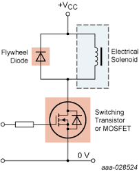
Add an flyback diode across the solenoid coil
The logic side should be fine
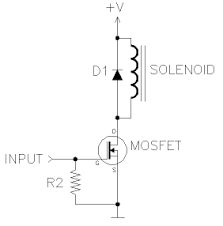
Thank you for your help/time. I'm just a beginner and I'm not sure what that configuration does. Doesn't that configuration allow the current to flow where ever it wants? Would you be willing to explain how it works? I pictured something like this because the electricity wouldn't have a way to by pass the diode but clearly I am miss understanding things. I appreciate any thoughts.
@AARAVmakes @AnonEngineering
In normal operation the diode is "reverse biased" and no current can flow (current flows "in the direction of the arrow"). When the solenoid turns off it generates a large voltage spike due to the magnetic field collapsing. That spike is in the opposite direction, so now that potentially damaging spike is "short circuited" through the diode.
OH WAIT! that diagram is bogus, mb 🙁
that's better
thats the same...you might have been looking at the one I made
which is what I thought in my head
hmmm, my original one was OK, where did you find yours 🙂
haha...I just made it..to show my thought
so the seloinoid closes...doesn't it still have a path directly to both sides that it can send electricity down in your diagram?
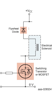
so when the MOSFET comes on the drain is pulled to ground and current flows "down" through the solenoid. It does not flow through the diode.
when it shuts off the "bottom" of the solenoid goes to a voltage above +V, at that point the diode does conduct
I think I am misunderstanding things a lot
Ok, so the mosfet is cutting the ground but the electrical spike originates from the solenoid correct? So its going to spike +V correct? How I see it, the solenoid as a direct connection to +V and the diode does nothing for that situation.
it goes above +V only briefly, as the magnetic field collapses
the solenoid is an inductor, the collapsing magnetic field induces a voltage in it
Inducing meaning increasing, so a voltage spike on the positive side, which the diode doesn't seem to do anything preventing flow
inducing means "causes to happen"
put current thru a wire, it makes a magnetic field
pass a magnetic field over a wire, it causes current to flow
that's why it is "electro-magnetism"
Ok. But still don't see how the diode stops the flow of current caused by the solenoid
It only seems to have an impact when the solenoid is not connected
it doesn't stop it, it prevents a large "backwards" voltage from destroying the MOSFET
Ok, a spike of voltage on the positive side that otherwise could damage the mosfet correct?
a spike of voltage (higher than +V) at the solenoid / mosfet junction
Ok. That makes sense to me. Thank you for your patience. It really makes a difference to me. I'm trying to understand but I can be a bit slow!
it isn't intuitive, no worries. google up "back EMF"
hey @hendr1x , Anon said everything. I just wanted to clarify for you. Theres this site called "falstad" where you can simulate almost anything simple and also share. I made a circuit for you just to illustrate what that diode does. And you are right, it prevents the current to flow, and thats exactly what we are doing, we are preventing it to flow in a direction and allowing it to run freely in the other. Check the link and play with the circuit so you understand. @AARAVmakes check this too so you understand what are those diodes doing in your board. https://rb.gy/qcp6q4
@alexsbmagalhaes : That is brillant. I didn't realize at all that is how the flow went when the diode is connected. I thought it was more like a check valve, not connecting a mini circuit.
it is kind of like a check valve...
nice simulation!