Dead Arduino Mega?
hi i found a arduino mega and after powering on it seems to work but not quite... there is no communication, the usb chip is desoldered and it looks like it has a blink code in it. but the build-in led is like more of the time on than off, the duty cycle isnt 50%. i should mention that it came from a 3d printer, using thermal camera i can see that the chip is heating evenly to 40*C.
Should i try to revive it or just buy a new 2560 and swap them? (i can solder SMD)
Is there a way to check if the chip is in boot-loop or just broken?
Im a newbie so please forgive me for my lack of knowledge.
31 Replies
Technically you don't need a USB-to-serial converter to program the ATMega2560 chip. If it's blinking the LED then the power supply part and the chip itself obviously work. So, you can also program it via the ISP (SPI) pins when you have an ISP programmer. You can actually also make an ISP programmer out of another Arduino, e.g. an Arduino Uno.
If it's about comfort, then nothing's better than getting a new ATMega2560 board with fully functional USB. Flashing the firmware via the ISP programmer does need you to create / have that ISP programmer and wire it up correctly, and maybe even an additional capacitor.
See
* https://www.avrfreaks.net/s/topic/a5CV40000000bArMAI/t394584
* https://docs.arduino.cc/built-in-examples/arduino-isp/ArduinoISP/
yea i tried to program it using isp but no results
ill try tomorrow one more time
or just right now
Well, there are many reasons why it couldn't have worked. Wrong wiring or broken wires, power issues, missing the capacitor on the programmer (https://arduino.stackexchange.com/questions/55498/when-using-an-arduino-as-an-isp-is-the-capacitor-required-or-not), selecting the wrong Arduino IDE options, ..
ill try to program it using uno with the atmega out
avrdude error: timeout
when i make a isp to isp cable to program a arduino using arduino i just need to connect pin 1 to 1, 2 to 2 and so on till 6 right?
The only way we're getting any further with this is, if we see the exact wiring connections between your Uno and your Atmega and make sure your have the ArduinoAsISP sketch uploaded to your Uno
and that you're ofc selecting the right programmer and using "Upload via programmer" in the Arduino IDE
You see the SPI pins there (CIPO = MISO, COPI = MOSI)
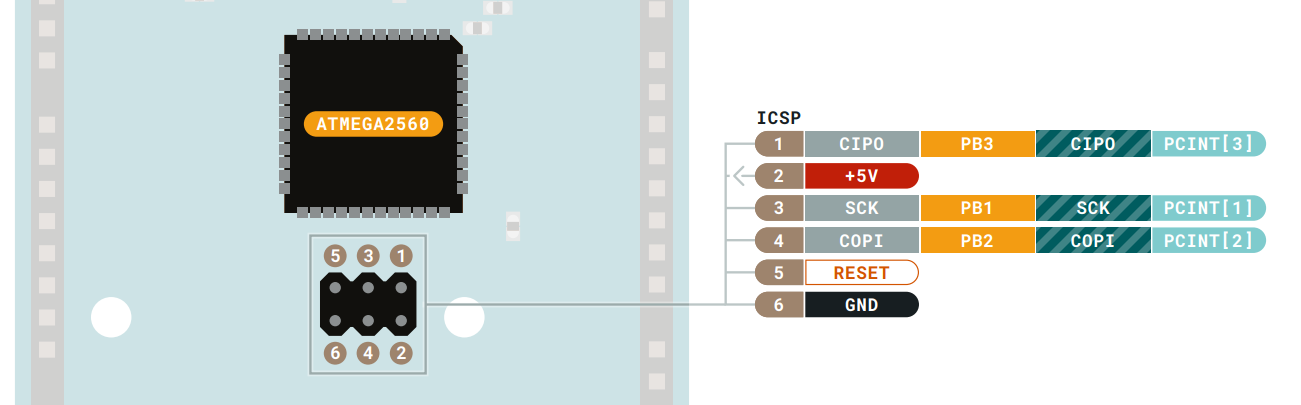
And you use the SPI pins of the Uno
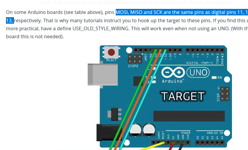
MOSI = D11
MISO D12
SCK = D13
And RESET to RESET
5V to 5V
GND to GND
And a capacitor on the Uno between RESET and GND
i have a uno board with atmega taken out, and a mega board with no usb to isp chip, so i took a female to female cables and connected pin 1 from uno to pin 1 on mega board, 2 to 2 on mega and so on till 6th pin on the isp connector
..huh?
ICSP*
how is this supposed to work when you have no ATMEga328P in your Uno that's not running the ArduinoAsISP chip
the connection of the ICSP pins between the Uno and ATMega is useless
because the Uno uses serial UART programming
it doesn't use the ICSP / SPI pins for programming
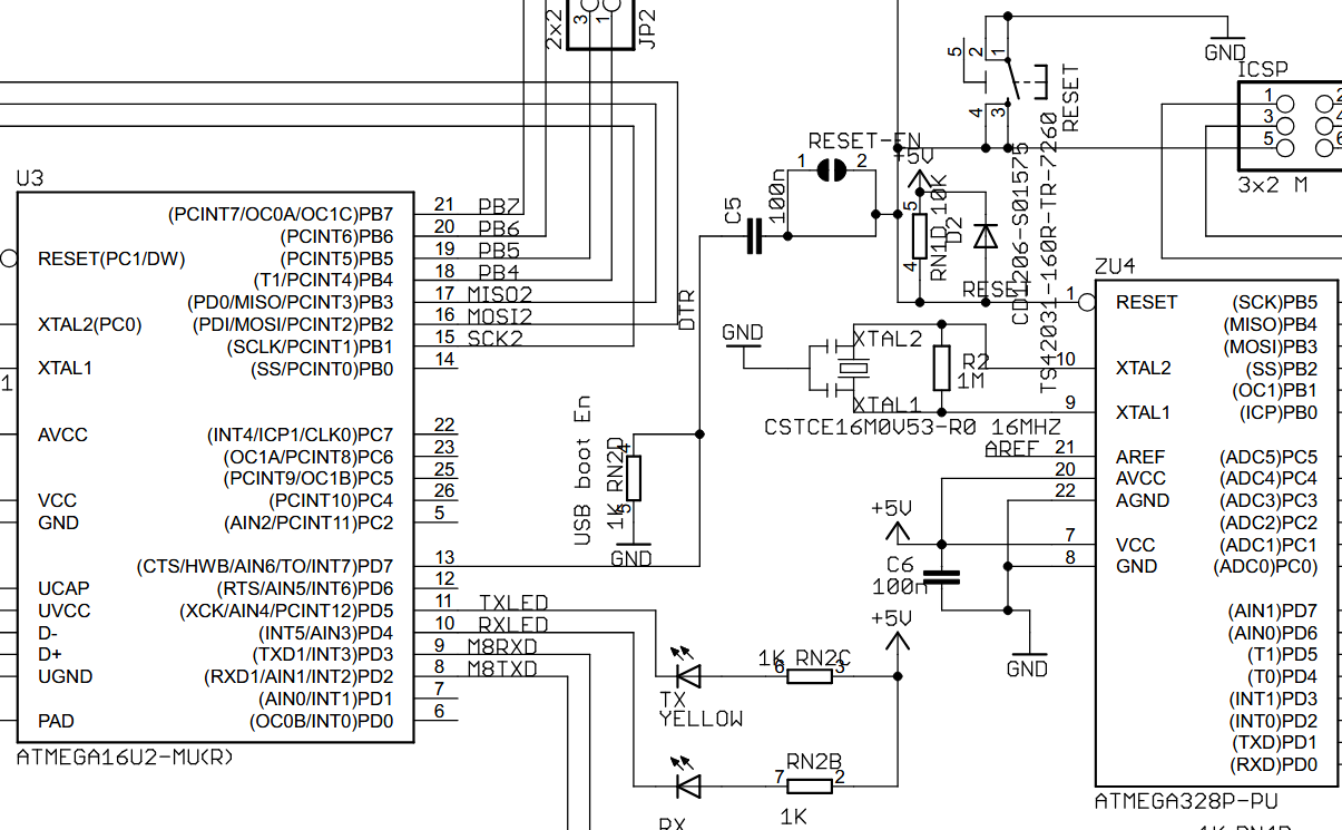
the only thing you could try to do is using your braindead Arduino Uno board as a USB to UART adapter
and pray to god that the ATMega2560 still has its Optiboot UART bootloader burned into it.
the only connections you'll need for that are D0 and D1 (TX, RX), RESET, 5V and GND
sorry for the mis understanding
ill dig for a usb to uart board
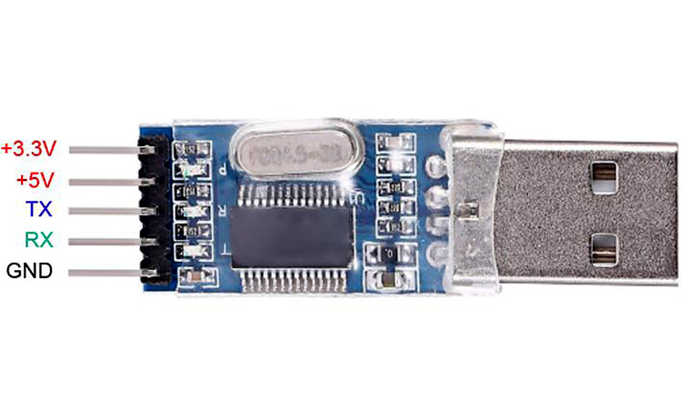
A USB to UART board should have TX, RX, DTR, GND and 5V
you may need to capacitively couple DTR into the RESET of your ATMega2560
pl2303
yeah sure
just follow this then
https://arduino.stackexchange.com/a/16522/30175
holy
man
i bought this board for like 3$ and the owner said it was broken
and it works
works just fine
thank you
So it uploaded correctly? And you needed to press the reset button to get it to upload / into Optifine bootloader?
can i buy you a coffe or something?
I don't have a link for that and I also don't need one, but lol thanks
wierdly i did not press anything i just uploaded and it worked
maybe you need to press it for the second upload. if it's running a sketch now, and not resetting, then it shouldn't enter bootloader mode on its own
you should be able to do is connect RTS to Reset on the board, using a 0.1 µF capacitor (in series).This is what circuit you should be using for auto reset Though I actually think it should be the DTR pin, not the RTS pin
DTR <-> C5 <-> Reset connection specifically.
yea it needs a reset at the right moment but it works!
Great! Another ATMega2560 saved.
Though that doesn't mean that other parts of the board are broken, idk. The IC and power supply seem to work though.
sadly i dont have a rst pin on pl2303 board so ill have to improvise
The PL2303 chip itsel does have the DTR pin
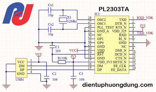
but many USB boards simply don't expose the pin
yea man ill probably add it myself
thank you very much man
sadly i have to go to sleep