Help
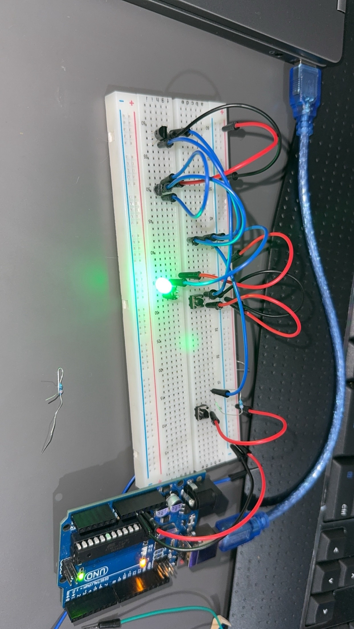
Hi everyone! Could someone help me draw a correct schematic for the circuit in my photo?
Goal / Logic
• Inputs: A and B are push buttons (2 legs each).
• Output: LED X should be ON when (A is pressed) OR (B is NOT pressed).
• Power: 5 V from Arduino (used only as a power supply, no code).
• Transistors available: BS170 (N-MOSFET).
• LED
4 Replies
.. if you have the circuit working in your photo, then you know all the connections. Just write them down with Fritzing oder EasyEDA or whatever schematic editor you like.
same as the other Help post from 10 hours ago
shouldn't it be something like this
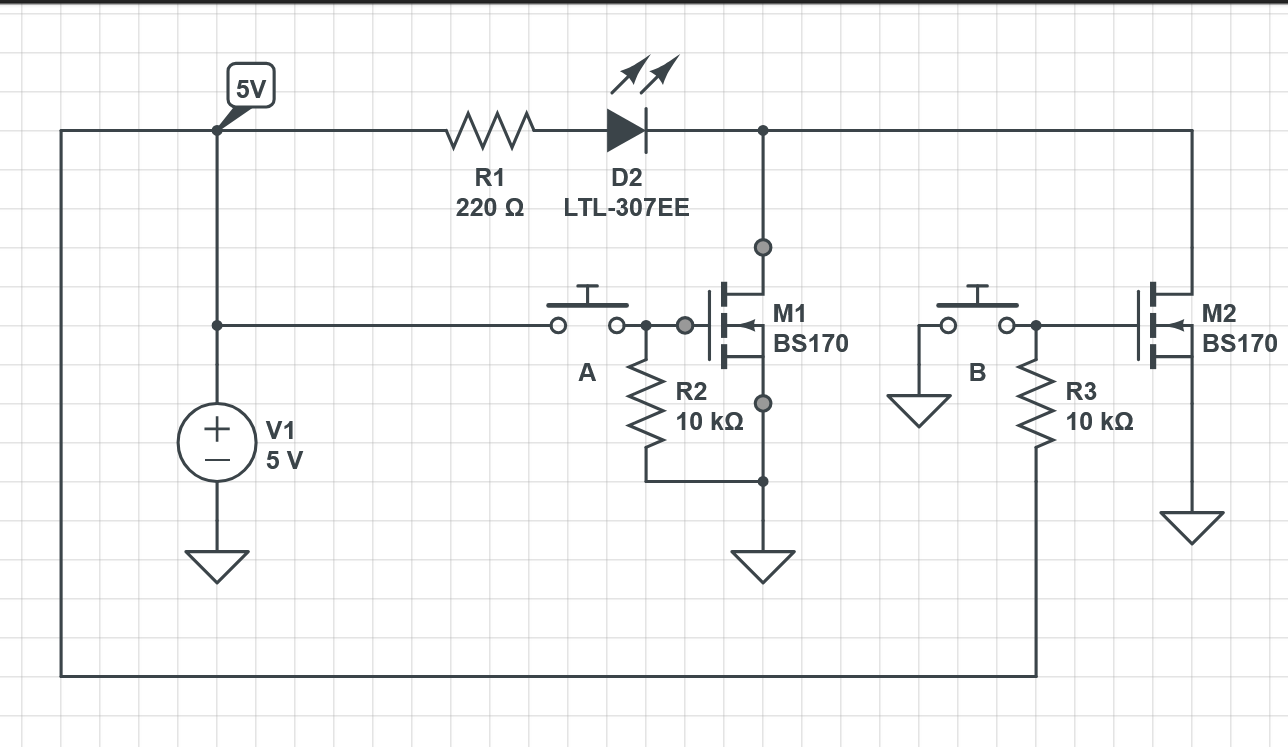
Give the LED two possible paths to GND
MOSFET M1 activates when A is pushed (and is off when A is not pushed)
MOSFET M2 is on by edfault and is turned off when B is pushed
since N-channel MOSFETs need HIGH signal to turn on (like 5V)