Need connections help for the electronics
I was doing a project at where the Nema17 stepper motor should uplift the weight of 300gms. Got the leadscrew,nema17-4kg.cm torque.
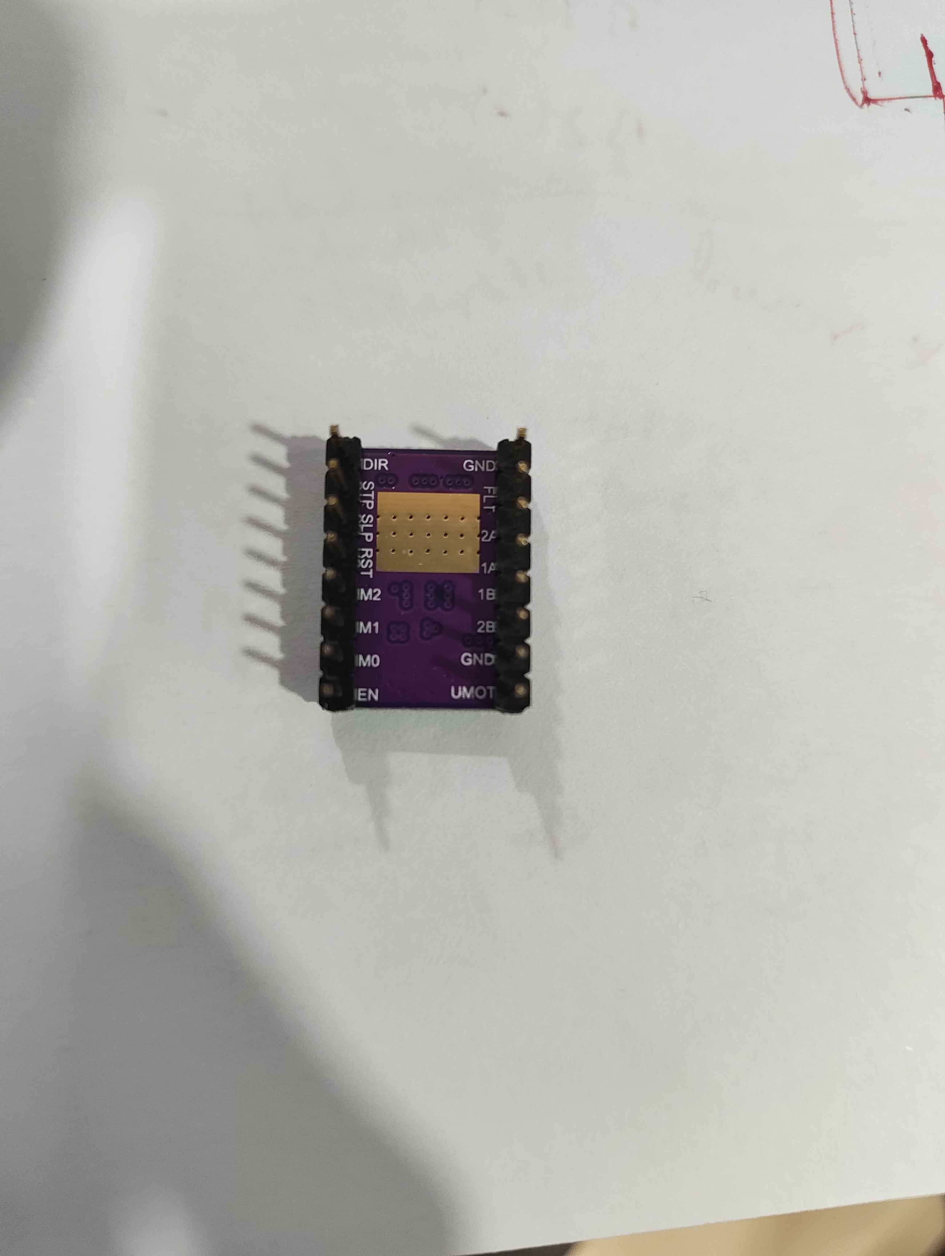
driver- DRV8825.
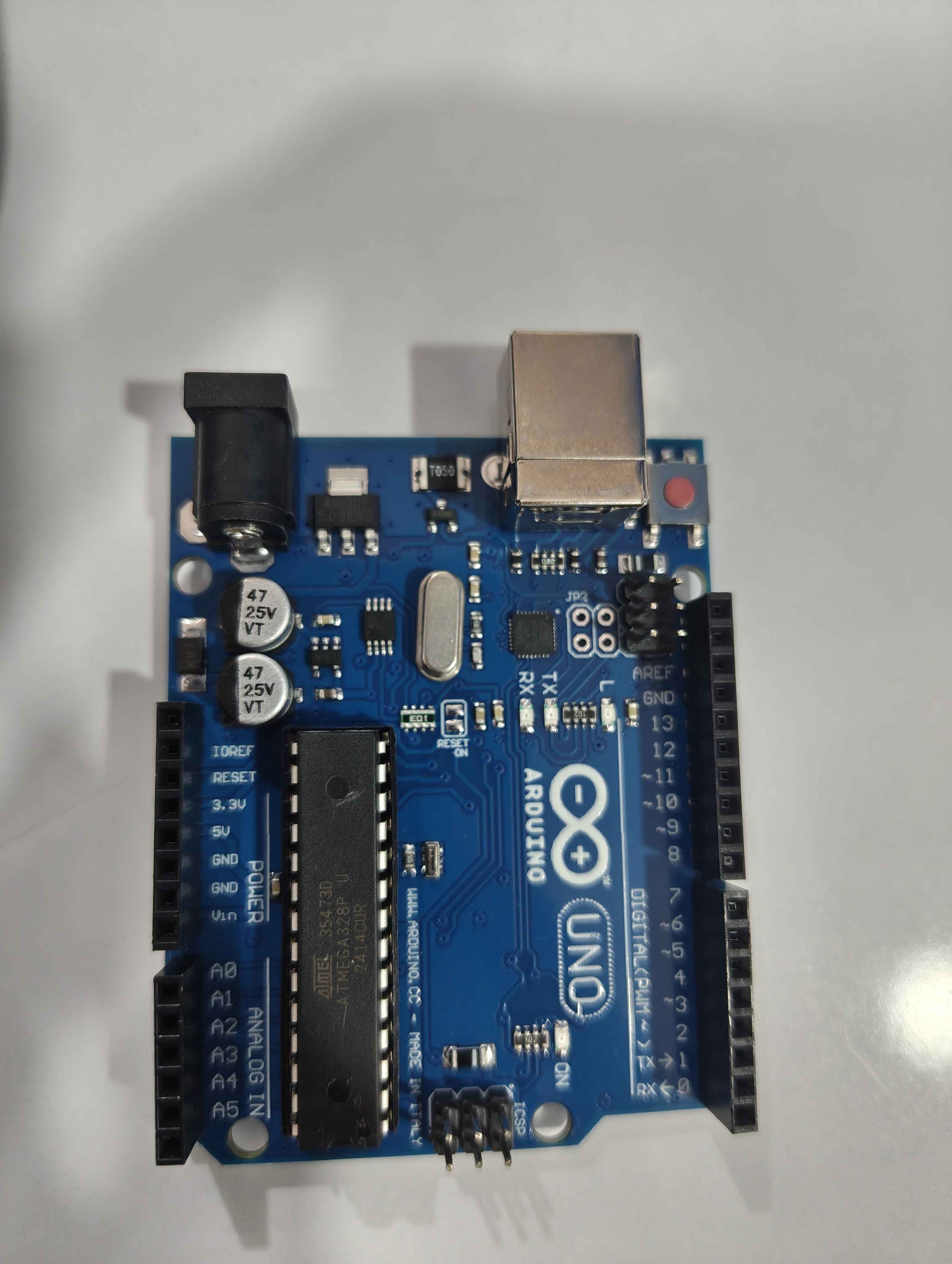
Arduino-UNO R3.
Adapter-12V,5A (input220v AC.output12V DC).
Screw terminal bar.
Now how to give the wiring connections & should I consider any hardware components??
Plz do suggest me on this, TIA
Plz do suggest me on this, TIA
15 Replies
Thats the kind of project I like. Very clear and hands on. So, you have everything you need there. You just need the wires. I will show you some pictures and tell you what you should care for:
Hey really thanks for your response
Looking forward for the pics
Np. So look at this. This is basically how your module interacts with the MCU and the motor. Notice this:
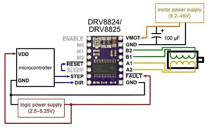
You have two power sources, one for you uC and one for your motor. You ideally should wire them apart from each other, and the motor wires away from digital data, as serial communications.
On your module, you see those pins names? Notice how some of them have a little "bar" stripe over the name? That means inverted logic. Ie. The enable pin MUST be grounded, or put into a LOW state for it the module to work. This is the same to all other pins that have inverted logic.
So keep that in mind, after powering you arduino and your module as on that picture, remember to connect both GND and then comes the logic: You need to setup the initial state of the module before you start sending it any information. Basically is: enable it, dont reset it, dont sleep it. When you done with that, you can send your module signals to control the motor.
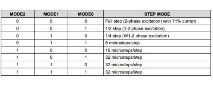
But at what resolution it will run? That is done using those M0 M1 M2 pins, that configure every microstepping option capable for that module, you can set one with jumper wires, for testing and later solder them directly to one state (0V or logic high 5V) thats in most of the cases enough, but when you get really experienced with it, you can change the resolution via digital pins on the fly with your arduino. Have a look at the truth table for the resolution:
Now you must connect your motor to the module according to its coils. If you have a 4 wires motor you have a straight forward connection. If you have 6 wires motor you need to adapt. I believe you have a 4 wires right? So each coil has one entering wire and one exiting wire. Much like positive and negative. You must connect one coil to A and the other coil to B. You can find out what wire belongs to what coil with a simple continuity test on your multimeter. The wires from a coil will beep or show very low to no resistance. The wire that doesnt belong to the coil will show up as an open circuit.
Now the fun part: you see those pins named DIR and STEP? Dir means the direction of the rotation and step is just like a clock, whenever the module see a pulse there, it will send a signal to your motor coils.
Now, I dont remember exactly if DIR = 1 means "turn clockwise" or "anticlockwise" but youdont have to either, just test it for yourself!
Because, if you see the motor yanking and shaking instead of running, it is very possible that you just wired one of the coils reversed. So just invert like B1 with B2 or A1 with A2 and it should work.
For testing I would download a simple test program that just spins the motor. Just for you to be sure that everything works. That's my two cents @Charlie
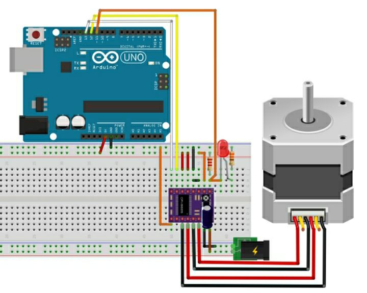
By the way, when you finished you should have something like this:
Hey Thanks for your response
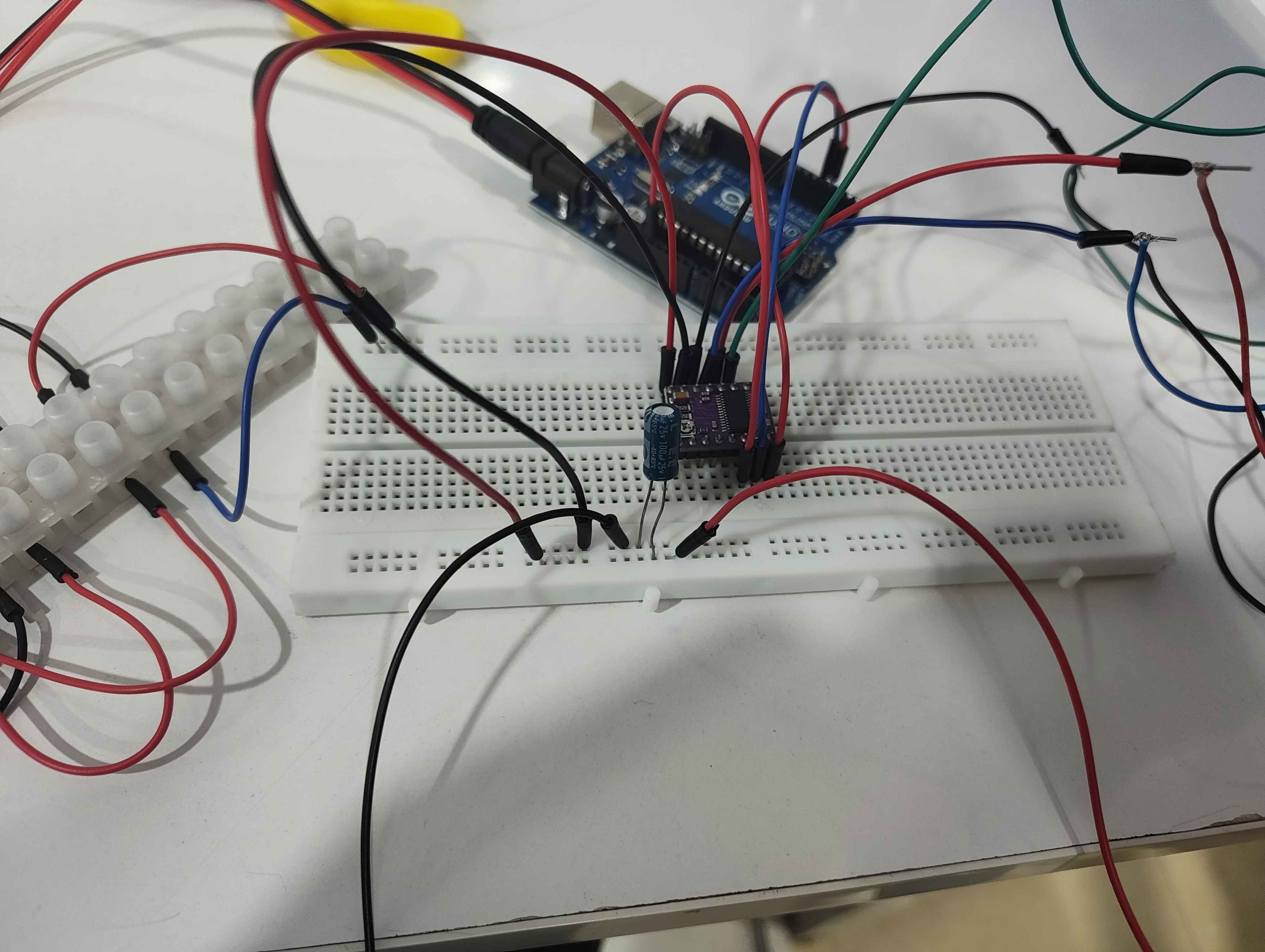
This is the way I did the wiring connections but it didn't worked. Later I came to know I have wrong wiring in the screw terminals. Then I updated the wiring. Today I should give the connections again. But I'm confused a bit.
There was a 5V pin on my Arduino. Where should I connect it on my driver??
The driver NEEDS to be powered externally. If you power it from the Arduino, you risk frying the whole board.
connect your driver with external power supply , because arduino can't draw the amount of current driver requires
@Charlie hello! I suggest you read again my messages, all you will need to make this work is in the very first image. Then if you have more questions, ask again 🙂
Heyy... Thanks guys I did it.
But the motor is just jettering, kind of making vibration, a small too & fro motion but not full rotation