Testing my matrix there is always a button that doesn't work.
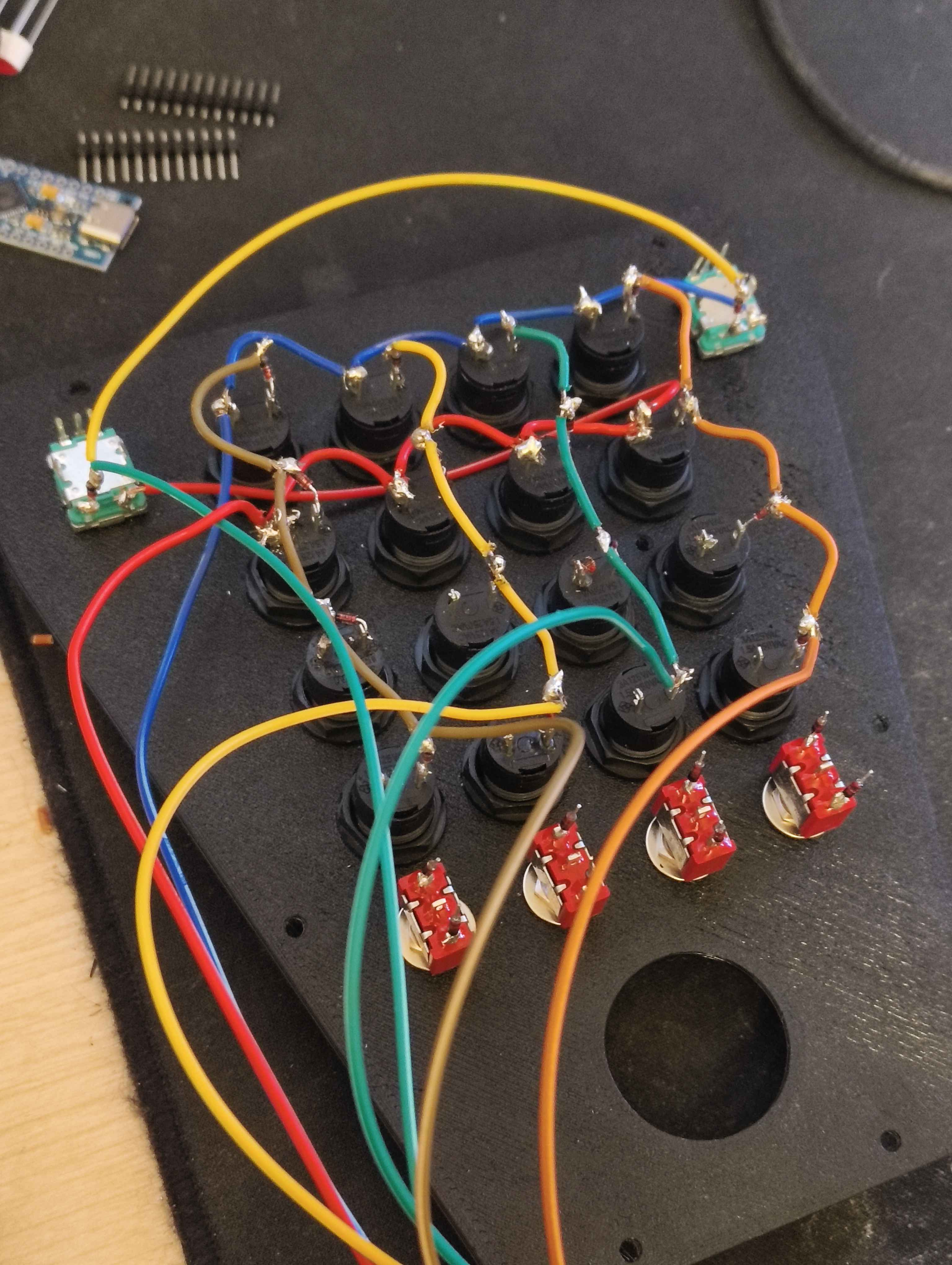
Trying to do a simple button box with arduino.
I'm testing my current wiring to see if it works in arduino. I set on my code to have 2 rows and 5 columns, I will add more rows in the future.
If I swap my cols or row pins in the arduino, the button that doesnt work moves position.
Sadly I don't own a multimeter, I resoldered the spots that could look weak/bad, so I'm assuming there is something wrong with the wiring.
My code: https://hastebin.com/share/imilaguvix.csharp
Hastebin
Hastebin is a free web-based pastebin service for storing and sharing text and code snippets with anyone. Get started now.
81 Replies
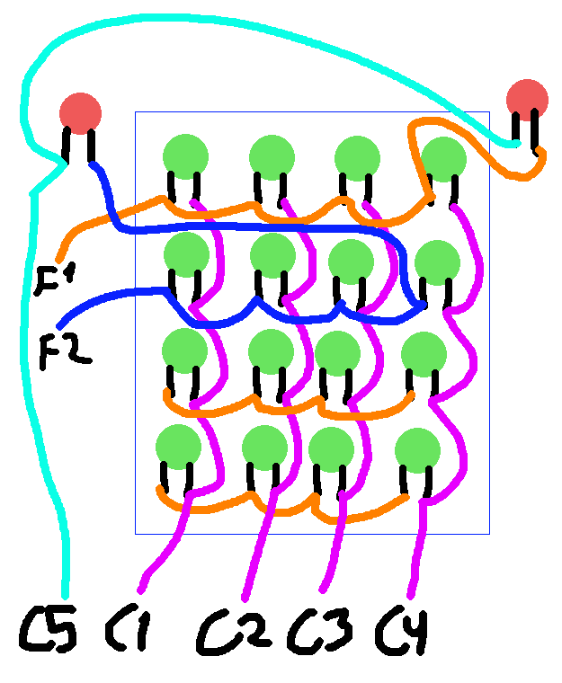
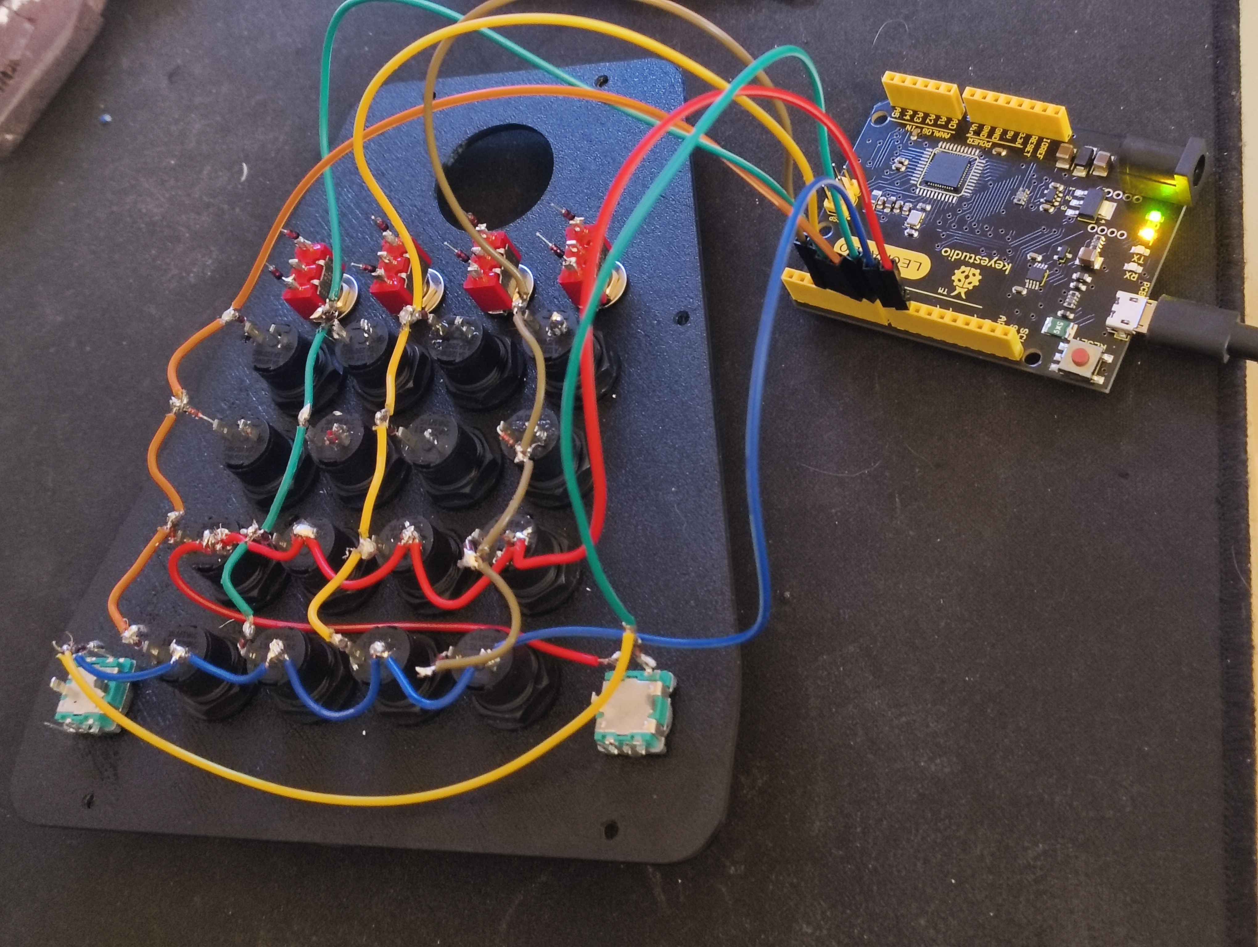
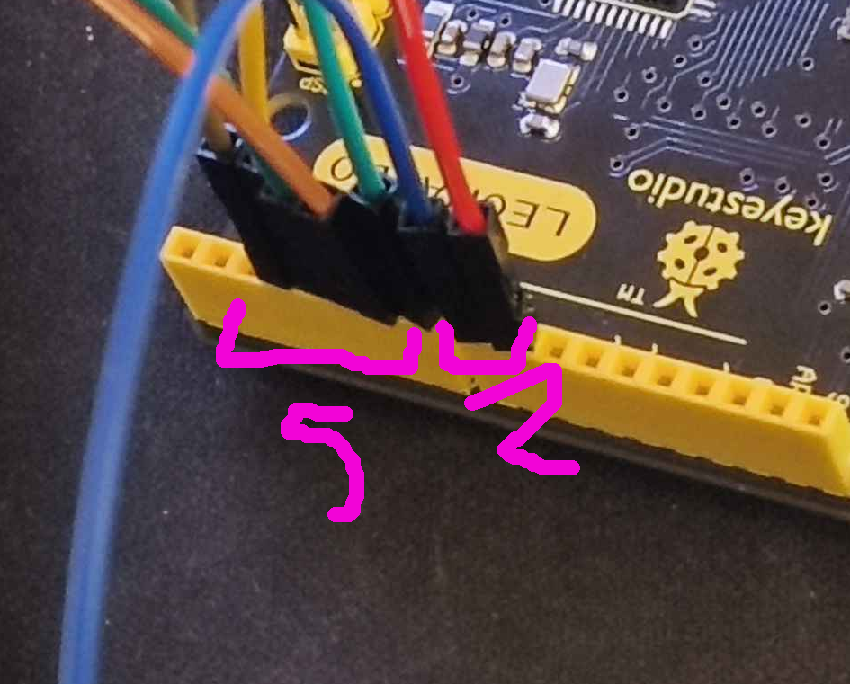
to make it a bit easier to understand and get help, this is how I connected the pins to my arduino (code remains unchanged):
c1, c2, c3, c4, c5: 7, 6, 5, 4, 3
row 1 and row 2: 8,9
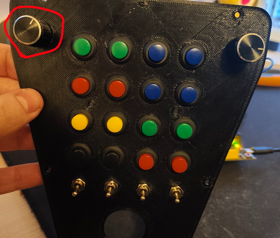
With that wiring, the button that doesnt work is the one in the top right in the images
the button is not the issue, since if i swap cols/rows around the one that fails will be another one
so is that button being read as alwayspressed? or is it just not registering at all?
Not registering at all
Since I didn't see any comments pointing to something very obvious on my wiring or code I decided to order a cheap multimeter
Its been years since I used one of those but I will assume I just have to put in continuity mode and check for every row and column connection
Its odd that its not registering at all
I kinda feel the switch might be wired wron in that case
I'm very confused on whats going on. The multimeter arrived, I checked every soldering point, they all work
I made some stronger and checked again, they are all good
I checked my amazon order and this is are the pins for the switches on the top

switch is the left leg, I have a diode soldered to those, diodes are in the colums
and i dont think those 2 are the problems, because if start mixing cols/rows, the push button of the rotaries will just fine
I will assume I dont need to solder the ground button between out a and out b just for testing the button press
So take your multimeter, run it through the diode and then through the switch to see if it trips. If not, swap the leads on the multimeter and try again.
Remember diodes are directional
can you indicate me how to do that? or you mean just check continuity? All my diodes are set in the same direction
I will recheck them all just in case
So if you used your mm. Rather the testing through the switch. Test throught the DIODE conected to the switch.
so i have to make sure there is conectivity between the leg and the other side of the diode?
to make sure everything is connected
You want to make sure it goes from the one side of the diode through the switch in the corect orentation
Diodes are directional.
so it matters which wire i use in my mm right
i should use the black one under the diode and the red one in the other side?
Yes BUT your going THROUGH the diode AND switch.
So one lead will get on the switch.
One lead will be on the legg of the diode that is NOT conected to the switch.
im sry but i dont know what u mean
I can not say it any clearer.
You are asking me to check continuity right
Correct. Ohms to be specific.
asking me to test resistance in this points to make sure all my diodes are working as intended?
Negative
? x)
Bingo
but sure I will test those, ty
Yes I understand. And be SURE to do that test with the encoder also.
this should always display 0?
If the button is pressed
then my wiring in inverted for those buttons? it will only show resistance under and on the top of the diode
but faik the buttons dont have polarity so it shouldnt matter
The configuration of your column and row wiring will dictate the appropriate diode wiring scheme and pin placement. This introduces several potential areas for error:
1. Incorrect pin assignment for diodes, despite correct orientation.
2. Correct pin assignment for diodes, but incorrect orientation.
3. Incorrect pin assignment and incorrect orientation for diodes.
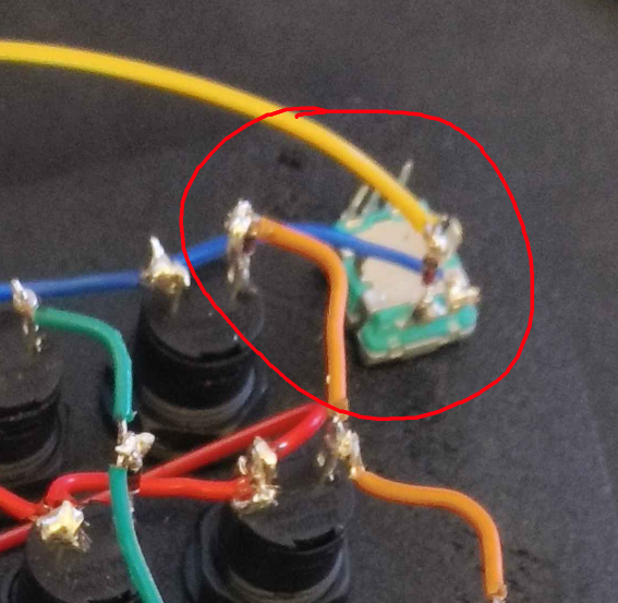
And all of this changes according to the wiring. But with the encoder. That has an orientation on its own. So now you have a diode, a wire, and a switch that ALL NEED to be wired in the corect orientation to EACHOTHER.
so there is a chance that the diodes in the rotaries are in the wrong way
blocking one signal making a button to not get registered on my matrix?
Yes or realy that you have the diode on the encoder on the wrong leg. Or backwords or backwords and the wrong leg. Or any of that and backwords wireing
the only way to check resistance for me is putting the red wire of my mm under the diode and the black one over it, with that way i checked that all of the diodes are working/showing the same resistance on every button
You have been telling everyone that you have switches and one switch is not working.
That is a lie.
You have switches. They all seam to be working you have an encoder with a button and THAT is not working.
If you stated that in the beginning you would had gotten much better help faster.
But with the encoder you need to go through the encoder also
im sorry but i dont mean what you say, can you tell me exactly what is an enconder? my arduino?
or just the momentary switch?
Encoder
yes but im only using the button function of it
and you can see those encoders in my first reply to the post
and in the post itself
so to clarify things up, im just testing the matrix with buttons and the button functions of those 2 enconders, im not wiring or coding the left/right actions yet
So when you check that one. Make sure you test it THROUGH the encoder
And to be sure I understand. Your normal buttons are operating. Your encoder buttons/switches only are the ones not working. Corect?
checking on my encoder, this is the only way to measure the resistance , shows 2.4 or so
if i start switching cols/rows in arduino, my both encoders will work
but a random button wont
Move your red probe to the other legg of the encoder. And test with the encoder pressed down.
Just for testing, I just reinverted the columns pins on my arduino, and now both encoders work just fine and the button on the bottom right wont work
and with button i mean a regular momentary push button, both encoder clicks work fine
Ok leave the wireing like that.
might be a code issue lol
for the loop to assign the buttons?
Now take your meter to the one button that's not working. Power OFF the arduino.
And test the diode to the button that is NOT working. And test the diode on the button NEXT to it.
okay so the code is currently untouched, the columns pins are inverted just like i told u. The button that doesnt work is on the one in the bottom right
So test the bottom right diode and then test the button just next to it
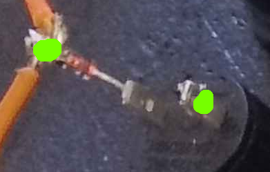
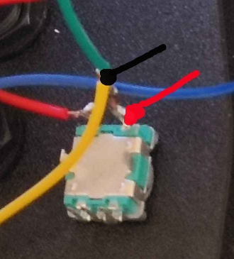
green one is the one that doesnt work atm, u want me to check pinks diode?
The arduino powered Down off
its currently disconnected yes
The green one is not working right now correct?
correct
Ok now check it.
Then check the pink one yes please
so every button will only show resistance with the red wire under the diode and the black one over the diode, in the same leg
and thats the same for both red and pink ones
But if you press the button down while testing. Is it the same resistance?
that might be tricky to test lol
Remember we are NOT checking the diode. We are checking the diode AND switch.
resistence between two legs, under the diode and when pressing the button right
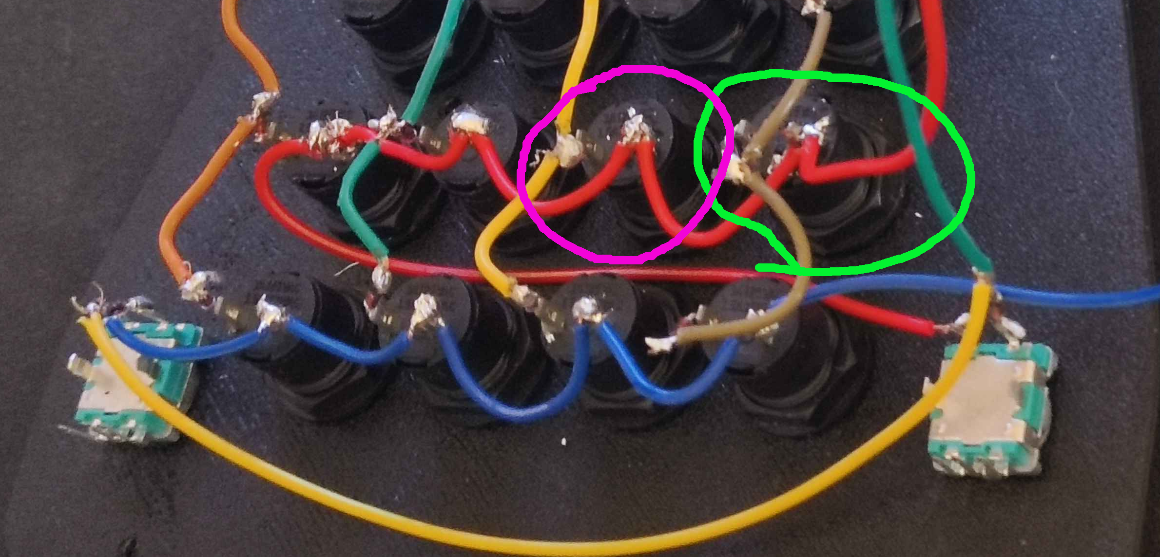
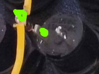
Like this with button pressed. The green button and the pink button
yeah
both have resistence when pressing then down
Same amounts?
Mor or less?
ill retest again and confirm
If so then in your code increas the column by 1. And see if that fixes it.
If no change then put column back and increase row by 1.
yeah i keep them pressed they both have around 24-25
same as checking diodes on the same leg
ill start testing code changes now
Ok so it seams like this wireing is the corect one. So note this wireing down.
now the virtuals buttons on windows match the order on my physical one
so thats good
i increased the num of buttons by one to make sure i wasnt missing one
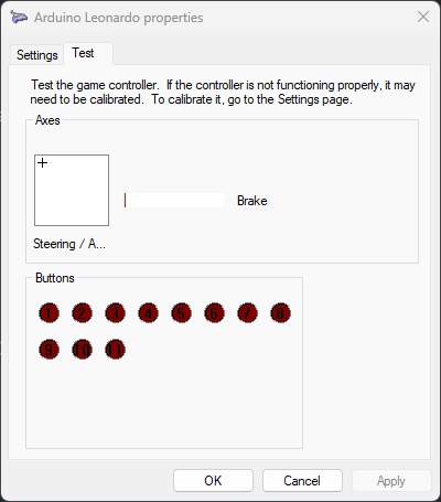
from 1 to 9 work, 10 doesnt work and 11 doesnt physically exist
https://cdn.discordapp.com/attachments/1433508550662946892/1433884726850224128/image.png?ex=690650b7&is=6904ff37&hm=fe760f140b56aa0407b34edab6e79aa59127fa5c4554c649b4551ab8ac0ba25d&
Going by this image I see. 6 total wires going to the arduino. Is that corect?
7, 5 rows and 2 columns
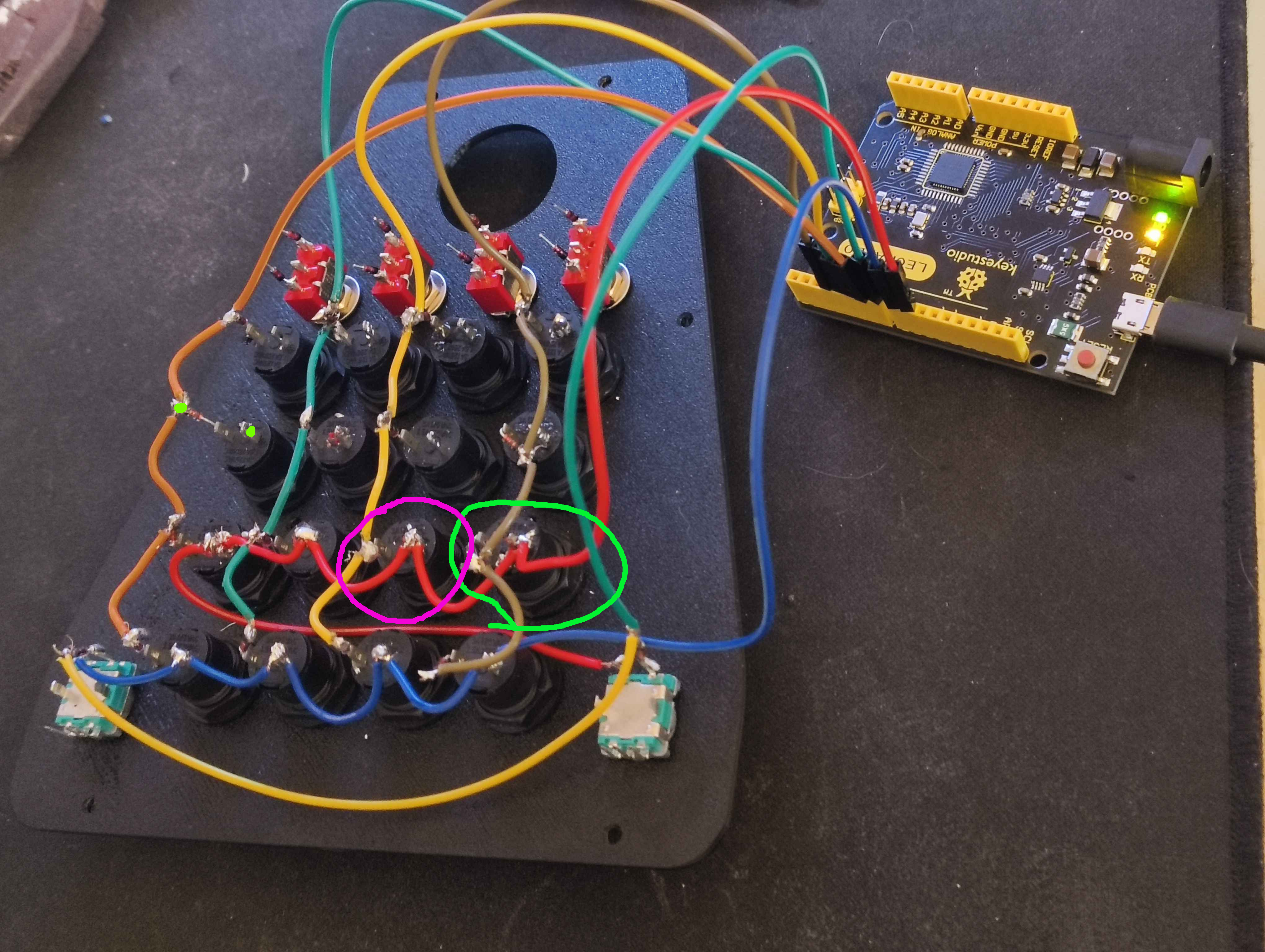
Ok
i used the gap in the arduino to keep them organized too
byte rowPins[ROWS] = {8, 9};
byte colPins[COLS] = {3,4,5,6,7};
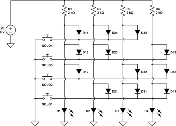
Ok so you will need to make a proper schmatic.
You can use easy eda. Or kicad.
But if changing the code the two ways a mentioned above does not solve it. Then you will need to make a proper schmatic.
It will end up looking something like this.
yeeeah
my char keys had an invalid character, 10 doesnt exist
it just works now using this:
so my wiring was always correct
But to summarize the error:
- I was using an array of key codes that I later transform into button ids
- The last one of my array was 10, and that's clearly not a clear key code/ascii character
Replacing 10 with A fixed it
Since my code is using
int buttonNumber = pressedKey - '1'; that means 49-49, so it will start from 0
Replacing 10 with A made my next button be 17 since the ascii value of A IS 65 AND 65-49 is 16
This is a simple function to make sure that I can make a table that makes letters get assigned after numbers, might be useful for someone in the future
and example of the usage would be:
Aaaaaand my issue is fixed, it was a dumb code mistake all along