Uneven belts tension and square xy
Hi. I keep struggling with un even belt tension reported by belt-tension script, but my x gantry seems to be perpendicular to y rail (checked by moving it to the front and measuring distance from extrusion by calipers)...
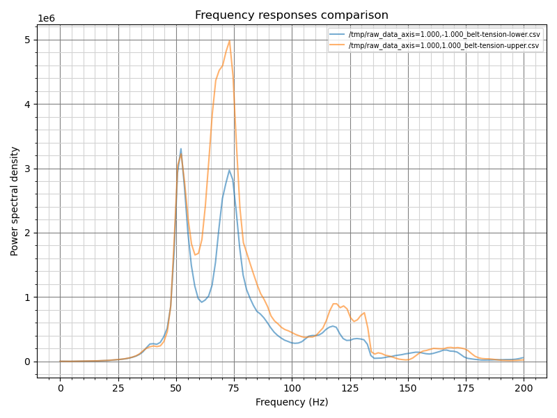
102 Replies
or should I just accept it as belt tension seems to much at 50hz?
This weird graph start to appear after I swapped xy-joints and top motor cages, so it did not just start to show up from nowhere, before it looked like that:
4.0 on 1e6 - that seems overly tight to me. mine is like 1.5
Oh, So I should make them less tight?
my shaper graphs if it might help:
I will try to unscrew both tension screw by two rotations then
Though @miklschmidt said on similar graph in #general that this is perfectly normal.. (4.0 on 1e6)
to each their own - I run mine at 1.5 and that works fine for me
and with less tension things will last longer
Got it. Running script after lowering tension by 2 rotations
I would also keep in mind - your machine will still print well even if things aren't perfect
welp, I lowered tension, but still keep getting same uneven results
If I try to tight lower belt, my x rail becomes not perpendicular to y rails
It says your upper belt is tighter than the lower one
yep, but if I change it - axis become not perpendicular...
btw, after lowering tension I got this:
you might have uneven belts or you didn't ensure your jointer plates are square
jounters plates are square?
Sorry, how whould I check it and fix it?
I used 123 blocks to hold the X axis parallel to the front of the frame with clamps and then tightened the jointers down
hmm, so your suggestions is to completly remove belt tension from the equation by loosing them completly and then try to reasemble xy joints?
The most important part of the belt tension graph is that the peaks line up
but they dont xD Hi
the difference in amplitude does indicate that one belt is stiffer than the other, this can be due to stretching.
the first one you posted did
Oh
It can also be caused by loose screws / parts etc etc
Or belt riding on idler flanges
etc etc
Okay, that is... intresting. Thanks
Hmm, it seams to get... Better? I lowered tension in both belts and then realign axes
Sorry for stupid questions and chaotic conversation, just have no expirince with that stuff,
Gotta start somewhere! 🙂
And I tweaked a bit more on got this… just a bit of turns back and fort
I looked into guide on how to read graph, and as you said - peak alignment is important, height is not
So I guess I will just stop on archived 😂 Or would you recommend try to fix it?
I would prefer https://discord.com/channels/582187371529764864/1100154509461835796/1100179903946690660 over https://discord.com/channels/582187371529764864/1100154509461835796/1100191522672099438
Just relax the tension a tiny bit on the lower belt there and you should be good.
If I interpret you right, you measured squareness of your gantry by using calibers to the front extrusion. If so then what you measured is not perpendicularity but whether the two are parallel to each other. Just saying because if your top plane is not really square but you take it as such, and then use that as a measure for your gantry perpendicularity, you're graphs are going to confuse you.
Probably you are right, but I tried my best during assembly of the frame, don’t know better method to check if axes are perpendicular😅
a decent machinist square or https://www.calculator.net/triangle-calculator.html
Triangle Calculator
This free triangle calculator computes the edges, angles, area, height, perimeter, median, as well as other values and a diagram of the resulting triangle.
Then I will try to get same results again😂 Thx
Okay. So, with such graph I have axes not perpendicular but at least 1mm, I checked it by machinery square and calipers.
And for this check I used same machinery angle which I used to assemble the frame, so this is for sure not machinery square fault....
I think that means your belts arent the same length
your belts are probalby binding somewhere
you should have 2 main peaks
means your belt grinds somewhere some metall or most likely plastik
forgotten shims can also be a cause
hmmm. Good guess, I did not make sure that I have equal belt lenght, as I thoough it wont matter
As there is decent belt tension mechinism, which works
hmmm, my carrege moves super easily
is this a 200?
It is 300mm
if you think your bvetls are fine then try to change the tension
you were almsot there
the left peak jsut should be a bit higher
not as high as the second one
It was at lower belt tension, and if I remember right - at that graph axes were not square…
I tried to check squareness of the frame by measuring diagonals, seems in +-0.25mm
this is the goal
But what is more important, equal belt tension or perpendicular axes?
both
equal belt tension, same belt length, squareness, ....
its all needed
Welp, if my frame won’t be square, equal belt tension not equal squrness
Or idk what makes my axes square at uneven tension
test if your belts have the EXACT same length
Okay, I will check for it, thanks
i mean really exact
like the exact same tooth count
But won’t tension mechanism compensate it?
How could I check belt equality without removing belt completely?
I don’t have fmmm mod and this is struggle to put it back in
Or there is no such way?
you cant
All clear, task understood
Thanks
dont do it now
try to get the FMMM Mod and then do it
Welp, my frame was not square, and my square is not square too as it report >90 deg angle on all corners
I need good machinist square before I put printer back together 🤡
I bough more reliable square, checked again, I some how have ~90deg angle at left and right top corner and >90deg ad back corners
How could this be possible?
some extrusions must be skewed
or unequal length, or/and with gaps
Hmm, maybe maybe, but unfertenatly, no method to check it. Kit is original ratrig kit.
what i mean is that you havent squared the frame well enough
As I remeber from trigonometry, it is impossible to assemble shape out of 4 sticks, which will have two 90deg angles and other two >90deg xD
So, ither sticks are not strait, or my top part of the frame is not in the same plane
but my bed mesh has only 0.15mm diff, so - I guess it is - in the ~same plane
You said ~90deg 😉
and not meaning to argue or prove my right, I thought it was helpful to give you something to check that you could have possibly overlooked.
yep. it is definitely helpful, thank you!
I thing I found source of all of mine problems
Just what the fuck
I have been looking into some random graphs
because mainsail did sort them like piece of garbage
timestamps on fs are correct btw
Wow that sucks 😟
ps. I just checked and have the same issue
sorted by name by default. ZERO always lists off first. Simply click on the ' modified' column title if you wanted it sorted by date. seems normal to me. Linux and windows both do that
Check ‘modified’ column, it is selected (arrow next to it)
But result is still sorted by names
In a terminal, when I use
ls -alht
, where t
sorts by time and, as the man page for ls
explains, uses modified time by default, the output for the input_shaper
files is different than in mainsail when clicking the last modified
column header. Its not sorting correctly IMO. @maba_kalox screenshot above shows its not correct.How could I measure belt tension without using macros?
I feel like something could be wrong with adxl or something else, because if I follow graph and tight until graphs matches, by hand I can feel that belts actually have different tension
There are people who use the microphone on their mobile device to measure the frequency when picking the belt like a snare on a guitar. Personally I don't trust that method for several reasons I don't want to get into, but you could give that a try. Did you ensure your belts are equal length? I mean, to the tooth, equal?
issue resolved, the reason seems to be - a table... Graph on table:
Graph on floor:
aside from the base for the printer (floor/table) nothing was changed, so gaentry is still perpendicular and belt tension was not changed.
Shouldn’t the Y axis have a second peak at ~40-50Hz?
it should, but I have no idea what could it be. I mean. I have small peak...
but something cancels it out. IDK what
That’s a bit better, yes
that is graph on the (fixed) table
by fixed I mean - I added/removed pads under the legs, to make it more stable
my shaper graphs:
though this boob on y axes around 60hz looks suspicious xD
The „hill“ around 50-70Hz on Y looks not right, yeah.
Did it move smoothly without the belts?
hard question, I aligned gantry by belt tension and only after fasten it
How large is your printer?
300mm
Then I think that the resonance frequencies are a bit low. It could be that both belts need to be tighter (by the same amount).
But maybe wait for experts on this, before you ruin it
As long as you don’t hear the belts slapping against the extrusions during resonance testing, it may be ok
Opinion differs, someone suggest to have 410^6 power density, someone sugges aroud 2 10^6
they slap xD
I don‘t mean the peak value, but the frequency, where the peak is
Ok, if it slaps, then it’s definitely too low
For me, tightning, change the peak height too
so, they should be, that tight, that during belt tension test they dont slap at all?
I was told that slapping during the test does not mean the belts are too loose.
Hmm. Lets wait for third opinion xD
by someone on the R&D team 😉
Yeah, better to wait ;)
But during normal printing they should not slap
I will try to print calibration cube with current tension, and check how bad is it.
they slap for me only on reasonance frequencies
So not all the time, but rather at peaks
That makes sense
best bet - take a video of this slapping and show it too us
Gates (the belt mfr) even sells a device for belt tension via sound. This method is ages old and widely used in industry. Even my CNC mill lists the belt tension via a resonant frequency (and it's a tiny center to center vs the RR machines.) Florent posted a great write up he did for the RR machines (BRS-Engineering website) He used Gates own belt data and the spreadsheet to produce the freqs for 300, 400 & 500 sized machines. It works spot on. I own a rather expensive mechanical belt tension gauge and the numbers match quite well doing the frequency method to the Gates specifications.
From Florent's doc.... peaks should be
300 86-100 hz
400 66-75 hz
500 53-62 hz
I personally am running right at 72 hz on my VC500 and get no belt slap on that belt section parallelizing the Y extrusions. I use to be able to watch the belts start vibrating during the resonance test. don't see it anymore.
MPE... YMMV
@ptegler I looked at their website and searched around for that write up and couldn't find it, if you have the link would you share that please?
Thanks, that was fast :D. I'll read up.
PS. Its not that I don't believe the method works or is unreliable, its phone microphones, apps and the procedure a person has to follow that I think is likely to produce unreliable results (hence i didnt really want to get into it 😉 ).