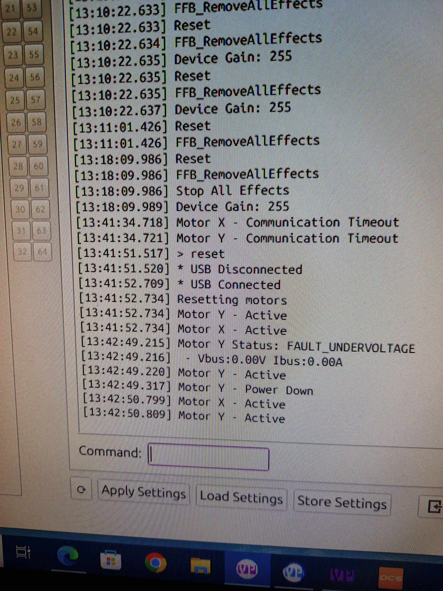
Hi! I have a problem with disconnecting the motors while playing, cant figure out if it is something
Hi! I have a problem with disconnecting the motors while playing, cant figure out if it is something to psu or software related

 MM
MM S
S D
D WW
WW W
W NDWDDWDDDW
 WN
WN
 N
N WNDDDWDWW
 DWWD
DWWD D
D WWNN
WWNN HHD
HHD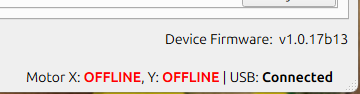 D
D S
S
 DDD
DDD WW
WW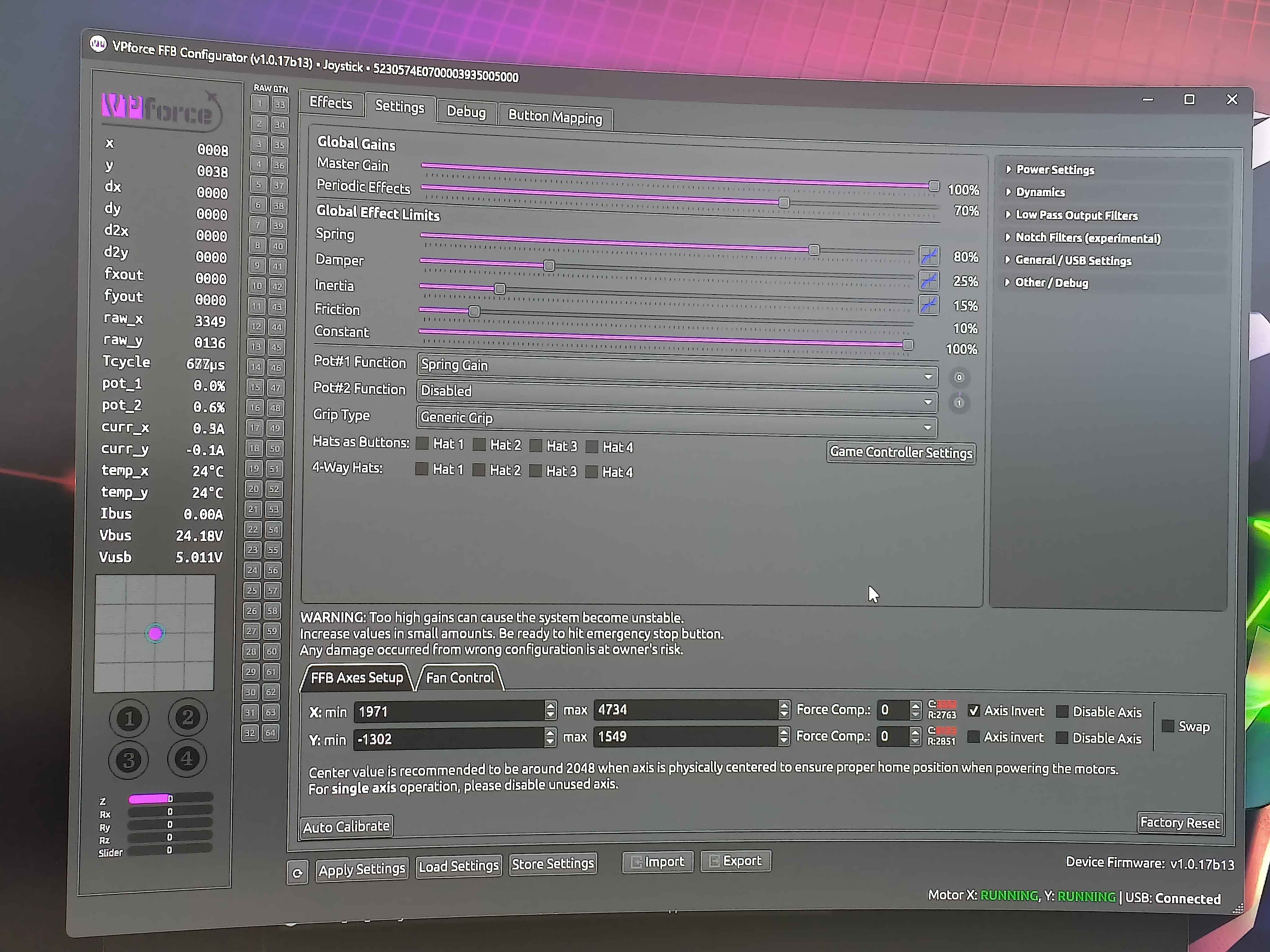
 TT
TT


