
 K
KYou add header pins to them. But finding the correct one is not the easiest

 B
Bwhat do they use to communicate?
Bi found this earlier. but i'm concerned with whether the display quality is gonna be the "best" for what's available right now
 B
B K
KI'd say depends on the display in question
 M
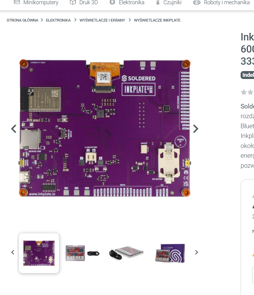
Mlooks like 7-colour eInk?
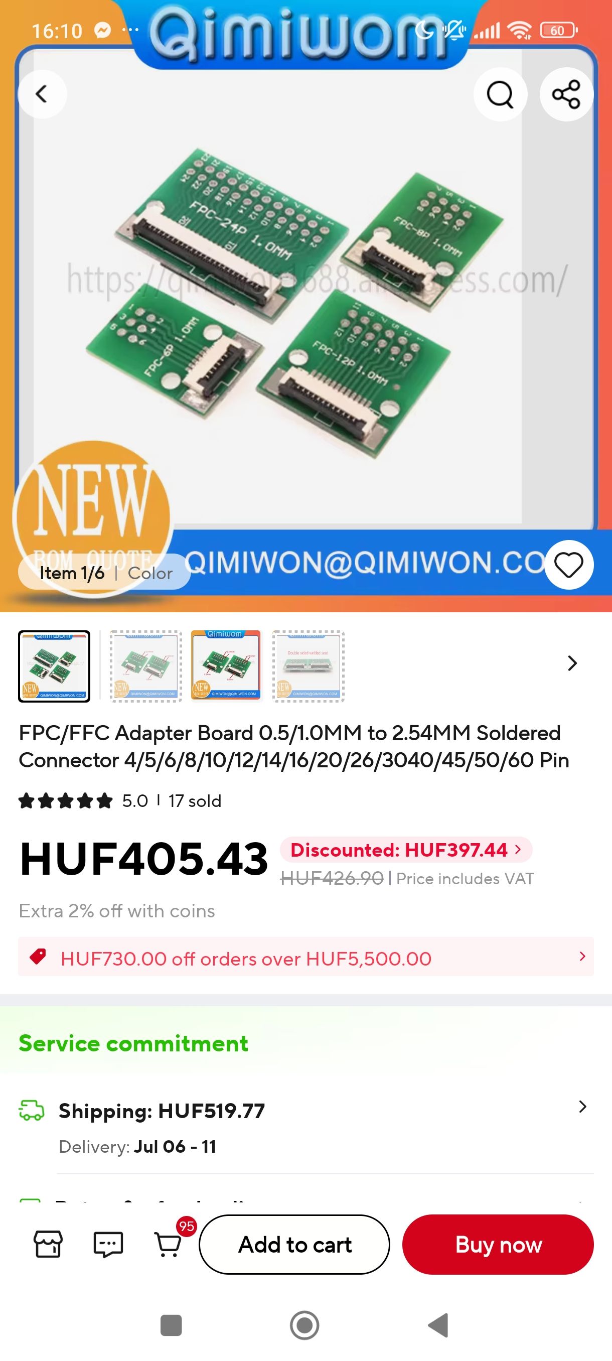
BFPC is just the cable right? I saw seedd studio makes breakouts but i'm not sure about their compatibility either
 B
Byes I need color and >5" that's about it
Mi wanted to get a 7-colour eink screen, but they're pretty hit and miss with actually looking okay
KSeems like that heavily relies on the pinout from the displays are all the same (which I highly doubt)
Mit depends a lot on what you're showing
Mi was looking at this one https://www.aliexpress.com/item/1005009192833553.html
Mbut its pretty pricey and its not great for showing pictures
 T
TNot on a breadboard... those max out around 1A current.
TMaybe. You'll have to not trigger these limits. I wouldnt cut the barrel off though; instead I'd get a barrel jack and wire it to a screw terminal so I could screw in whatever wires. With a fuse too.
 T
TWhat are you trying to power?
THowever you make the connection is up to you and depends on the application. Yeah, 16A is around the max capacity. You don't really want to run it at 100% all the time...

 T
Twould 100% be considered 16A or 20A
TAlrighty. Because 240W is substantial power for hobby stuff I'd still be taking the connections seriously. I'd be worried that if you don't know about current on a breadboard, you don't know enough yet to be playing with this safely. Please be careful.
You need something that isn't going to short, and is a solid mechanical connection that isn't going to heat up (a bad connection can start a fire). If you know how to properly solder and heatshrink the wire connection, and its going to a single wired device that needs 16A, and the wires are all appropriately sized on both sides of the connection, that's fine. But be safe about it.
What are you powering?
TDo they have motor drivers?
TAlrighty. Take a look at this wire gauge info https://www.electricaltechnology.org/2022/04/american-wire-gauge-awg-chart-wire-size-ampacity-table.html See how big the 12 gauge vs 24 gauge wires are?
ELECTRICAL TECHNOLOGY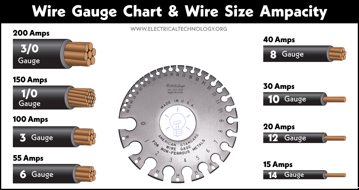
AWG - American Wire Gauge Chart - Wire Size & Amperes Rating Table. Wire Gauge Size Ampacity Charts and Tables. How to use a Wire Gauge?
TMost breadboard wires/jumpers are 22 or 24 gauge.
TYeah. So what you want to do is basically setup a fuse board. Each individual motor has a max current that is safe for it, and the main panel supply power is split amongst those motors. The main power (this input) is also protected. You can read all about this here.. https://literature.rockwellautomation.com/idc/groups/literature/documents/at/ic-at001_-en-p.pdf this is more written for bigger industrial motors but a lot of the same ideas apply.
Ti'll dig through this, thanks gng
Tyou're chill as heck
 T
TEh, everyone has to learn about it sometime.
 J
Jmini and micro b are both electrical similar, no?
Jonly difference being mechanical (aka the shape and placement of connectors)
 R
Relectrically identical.
 T
Tsince you're only using it for low speed USB 2.0 speed serial communications it doesn't really matter which you choose @GasolineSmellah since the standard simply requires you have 2x power + 2x data wires...
 effectively it's just different connectors that can be used for the same purpose...
effectively it's just different connectors that can be used for the same purpose...Ttechnically any 4-pin connector (even 2-pin connector) can be used on your microcontroller module side...
T using USB-specific connectors just allows you to use off the shelf data cables rather than to have to make one yourself...J
say I had 2 level shifter modules. I don't have to use 3.3 v and 5v. I could put 5V on the LV side and 12v on the HV side, right? The idea is to transmit UART (or other protocol) over longer distances.
Jhttps://www.ebay.ca/itm/267126230465 example level shifter module
eBay
Find many great new & used options and get the best deals for 6 x Logic Level Converter 4-Channel 3.3V-5V Bi-Directional I2C ISP ICSP at the best online prices at eBay! Free shipping for many products!
 A
Ai'd use a "TTL to RS232" adapter, RS232 will go 100m
i suppose in principle the level shifter would work but good luck figuring out if rando module will tolerate 12v
i suppose in principle the level shifter would work but good luck figuring out if rando module will tolerate 12v
 D
DGo current loop - goes further...
 F
FHello everybody. I'm new here and I wanted to make sure I am asking my question in the right channel, so please guide me to do the right direction if this is not the right place for my message.
I am newby when it comes to electronics and arduino, but I work as a web dev for 2 years now, so I have some programming knowledge. I started working on a rubics cube algorithm teacher robot, for which I first used the cheap 28BYJ-48 stepper motor with the corresponding ULN2003 driver. It turned out to be too weak for turning the faces of a rubics cube. I first experimented with designing gears for it, but it was unreliable so I decided to go for a more expensive stepper motor and driver. My choices were a 5 pack of Nema 17 motors from StepperOnline (P/N: 17HE15-1504S) and a 5 pack of DRV8825 drivers. Since I am not planning to run all the motors at the same time, I bought a 24V 6A power supply. I did my research (as good as I could) and found out that the motors are rated for 1.5 Amps, so I adjusted the drivers to have 0.75 VRef (given the formula Vref = rated current / 2). I have sticked the heatsinks to the IC, but nevertheless the temperature started to raise quickly (I touched it with my fingers and it was unbearably hot). Because of this reason, I adjusted the Vref (with the motor being disconnected) to just 0.25 V, to experiment with it without accidentally frying the IC. This seemed to solve my problem when I had my motor in a stationary position, but as soon as I uploaded a simple endless rotational script to the arduino, the heatsinks started to heat up again, though this time, not that much, so I decided to measure the heat with my multimeter. While th motor was running the heat was crawling up continously with a steady phase, and it reached around 80°C in around 20 seconds of running. This was the point when I turned off the device, because I have read it in the datasheet of the driver, that it can only handle 80°C safely.
I am newby when it comes to electronics and arduino, but I work as a web dev for 2 years now, so I have some programming knowledge. I started working on a rubics cube algorithm teacher robot, for which I first used the cheap 28BYJ-48 stepper motor with the corresponding ULN2003 driver. It turned out to be too weak for turning the faces of a rubics cube. I first experimented with designing gears for it, but it was unreliable so I decided to go for a more expensive stepper motor and driver. My choices were a 5 pack of Nema 17 motors from StepperOnline (P/N: 17HE15-1504S) and a 5 pack of DRV8825 drivers. Since I am not planning to run all the motors at the same time, I bought a 24V 6A power supply. I did my research (as good as I could) and found out that the motors are rated for 1.5 Amps, so I adjusted the drivers to have 0.75 VRef (given the formula Vref = rated current / 2). I have sticked the heatsinks to the IC, but nevertheless the temperature started to raise quickly (I touched it with my fingers and it was unbearably hot). Because of this reason, I adjusted the Vref (with the motor being disconnected) to just 0.25 V, to experiment with it without accidentally frying the IC. This seemed to solve my problem when I had my motor in a stationary position, but as soon as I uploaded a simple endless rotational script to the arduino, the heatsinks started to heat up again, though this time, not that much, so I decided to measure the heat with my multimeter. While th motor was running the heat was crawling up continously with a steady phase, and it reached around 80°C in around 20 seconds of running. This was the point when I turned off the device, because I have read it in the datasheet of the driver, that it can only handle 80°C safely.
 F
FCan anybody help me please, to find out what I have done wrong, or how I could fix my heat sink and IC getting hot, or if it is normal for drivers to get this hot under load? I gladly provide images and more information if it is necessary, I just ran out of characters in my previous message and I don't want to include too much information about the nonrelated stuff (and being a beginner it's hard to decide what is relevant  ). Thanks in advance for anyone who is willing to help
). Thanks in advance for anyone who is willing to help D@Fragler might need wiring diagram. 24v seems high.
 F
FI will provide a wiring diagram in around 2 hours (currently still working). Can you explain why you think 24V to be too high? (I'm not saying you are wrong, I'm just curious  )
)
)DIt's just at the max for the stepper. Should not really be an issue.
Rok,so you did the right thing with reducing your Vref first...we generally only set current to "max rated" if we are punishing out motors with a load that we should have bought bigger motors for...