IDEX VAOC Alignment problem - dual color
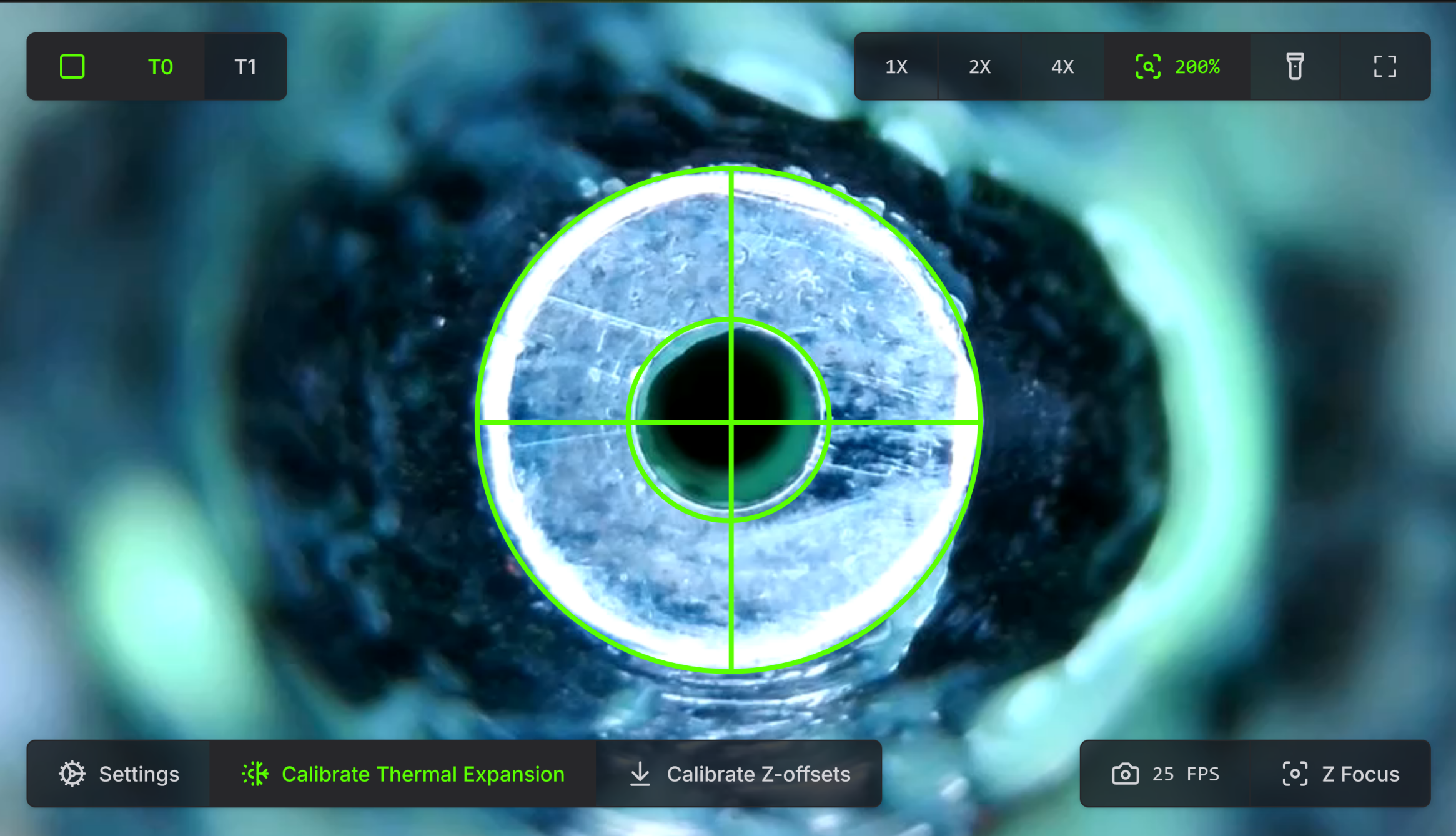
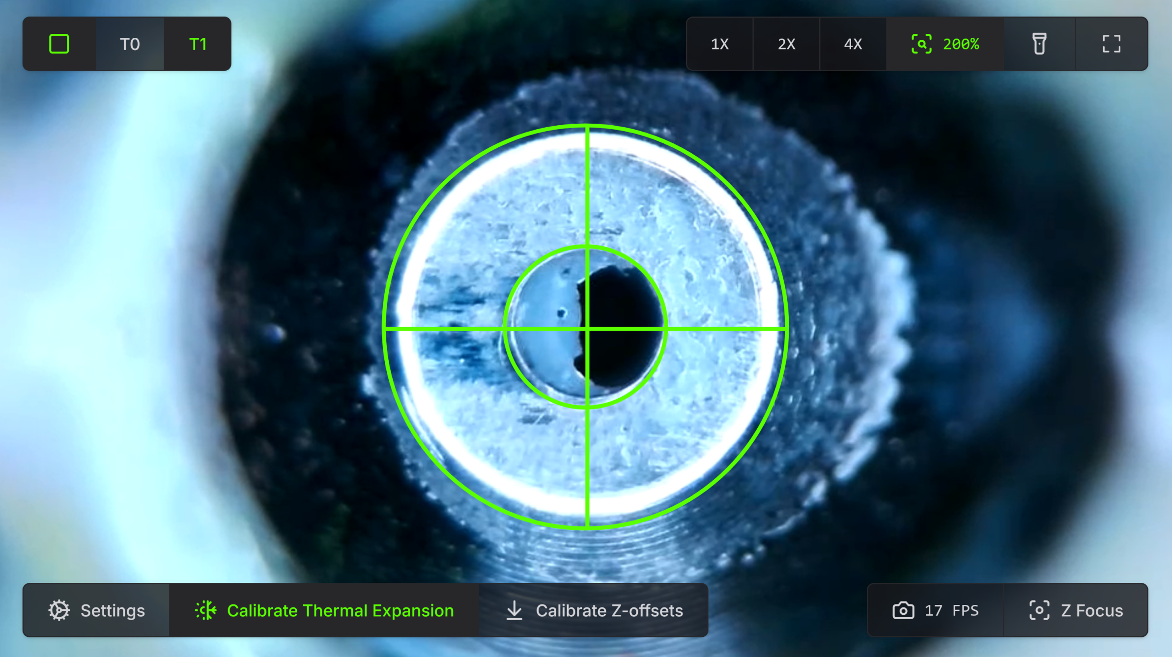
VC4 400 IDEX just finished commissioning. Ran a dual color calibration cube and the 2 parts are off, primarily on the X axis, by approx 0.75 to 0.8mm. 0.4 nozzle, so any small off-center in these particular images is a small fraction of 0.4mm. T1 is printing a full 2 nozzle widths to the left.
The VAOC commissioning guide has been followed, and VAOC calibration done numerous times. CALCULATE_DC_ENDSTOP output has been copied to Printer.cfg and done more than once in hopes that it would work. I now have 4 identical cubes that look like this. Green is T0, Grey is T1. T1 is always laying down 0.8mm to the left side.
X stepper set screws are tight, belts are not slipping from the CNC belt clips. No loose screws that I can find.
Really at a loss. I see Helge Keck is no longer here, but I sure hope someone can assist. IDEX is the entire reason I bought and built this machine. DC Endstop output: [dual_carriage] position_max: 459.560 position_endstop: 459.560 [gcode_macro RatOS] variable_bed_margin_x: [59.800, 59.560] [gcode_macro _VAOC] variable_expected_camera_x_position: 163.126 variable_expected_camera_y_position: 429.744 [gcode_macro T0] variable_parking_position: -57.800 [gcode_macro T1] variable_parking_position: 457.560 [gcode_macro _LED_START_PRINTING] gcode: Note that I left in the prior values for the DC Endpoint, commented out in printer.cfg, for reference. Parts printed identically. Any assistance would be welcome! And thanks in advance.
32 Replies


I haven't touched an IDEX machine but that sure is off :/
Yeah, it's kinda messed up. But the VAOC camera is pretty happy about the entire thing
It's be much cooler if I was actually shooting for two level effect with a part down the middle (Monty Python & the Holy Grail)
Maybe you need to print a a herring
Chop down all the trees in the forest with a herring?.....It can't be done!
I haven't gone through the commissioning guide or the build guide with a fine-toothed comb, is there a troubleshooting section like "if your nozziel is off, double check these three things"?
ooh, if you print that cube in all 4 corners of the bed, does the offset remain the same?
maybe theres a skew or a error in scaling something
I have not tried to print in more than the center location so far, but that sounds like fun.
There's some help if the nozzle won't focus, or if you get an out of range error for the XY, as well as if you are having problems with the Z offset between nozzles being too great.
Z offset is another thing. It tells me it's -0.65 or so, but I measured using gage blocks and feeler gages with both nozzles at the center of the bed and they were within 0.001mm. So not entirely sure how much I trust the whole VAOC setup. At least not mine
@TheTik Here is a 4 corner plus center print of a dual extruder calibration part I found on printables.
There is definitely a difference in different locations. I've not yet plugged in skew correction, but will do that soon.
It seems like a super interesting way to look at this problem.

This is a close up of the middle one, marked with a C for Center

Printables.com
Offset XY dual extruder - Idex calibration by LMaker | Download fre...
Calibrated your X Y offset on your dual extruder printer | Download free 3D printable STL models
Yeah, I'm just trying to think of how to narrow down the cause
@TheTik I checked the X stepper set screws and they are tight, and Loctited. Same for all the toolhead, XY joiner, etc screws. The belt clamps are tight and the belts don't seem to be budging.
One thing I've figured out. During VAOC calibration, you click back and forth between T0 and T1 several times to dial in the centering of the nozzle in the crosshairs. Every time you switch between T0 and T1, the head moves from one to the other so it can be over the VAOC camera. You keep doing it until they pretty much stay perfectly centered when you go from T0 to T1 and back and forth.
After a couple of iterations, T0 stays pretty locked in.
T1 does not lock in to a position. I will get it centered 2 times in a row, for instance, and then when I click back to it, it's off by a huge amount again, like 0.5 to 1.0mm or so. Investigating, I could easily move either toolhead with slight hand pressure - I could see on the computer screen that the nozzle would move off center.
- T0 would bounce back to the center of the crosshairs when I let go of the toolhead.
- T1 would more easily move off center, and bounce back to a new position. The Y position would be close to perfect, but not the X. The X could be off center to the left or right by a lot when I let go of the toolhead. When I applied pressure to the toolhead, it looked like the belts were flexing. The X belts are very low tension. So maybe the belt was not centering the toolhead as well as it should be? I increased the belt tension, same on both sides, and reran that test with the (5) L-shaped dual extruder test parts. Unfortunately, the tighter belt did nothing. I got the same poor results as with the previous set of parts.
The ease of moving is interesting, sounds like a path to keep chasing down
@TheTik I don't really have much of a path to chase. I tried more tension...I guess I could try even more, but I know that will simply cause worse IS from previous attempts. I have a Hiwin X rail on order because the factory X rail may be an issue with looseness on the T1 carriage. I suppose this could be related.
If it's a belt or rail/carriage thing, then I'm trying to understand what is different when the gantry is all the way back vs all the way forward. The X offset error between the 2 nozzles is only 0.4mm when they are printing those (2) rear calibration pieces. But it's much higher as it goes towards the front.
...
🤔
ok, I may have answered my own question. I just kicked off a new IS test since I increased the X belt tension.
As it started the test, it did homing and moved the carriage all the way forward to the stops. When that happens, the umbilicals get stretched out as the heads move further away from where the umbilcals mount to the rear extrusion base.
When outstretched, they are pulling on the top of the toolhead which may be causing the toolhead to tilt back and at an angle because the carriage isn't tight enough
That could be at least a part of it, well spotted
Zero progress, Have done
- lots more playing with belt tensioning
- tweaking X and Y belts for T1 to make sure they are dead center of the idlers
- checking everything for tightness
- removing some extra zip ties on the umbilical
- adjusting the PTFE tube on T1 so it's not rubbing against the rear extrusion when T1 is over the VAOC camera
- moving the VAOC from the Hub hat to the Pi,
- printed with both PrusaSlicer and Orca.
I can flip back and forth between T0 and T1 repetitively, and eventually it settles down to where it's repeatable, I hit the square box to save it, and most recently even did the CALCULATE_DC_ENDSTOP and wrote the new code outpu into printer.cfg
Why does T1 line up on VAOC, and then is off by nearly 1mm on the X axis once it starts printing?
Simply cannot solve this. Help is really needed.
..
Wish I had more to contribute, I've not done anything with IDEX :/
@TheTik Not your fault.
Somebody at Ratrig must know something, right? It's a real company. Shouldn't someone from RR with in-depth knowledge of IDEX be here on the ratos support channel to assist customers? Or is this Voron?
@RatRigMig
this is an unofficial discord, and they just had a fire, so I wouldn't hold my breath.
@TheTik Yeah, I know about the recent fire.
But I never saw them active here prior to the fire, either, except for Helge. When I asked Tiago who to email at RR for technical support questions a month or 2 ago, he said to post here. Literally, the unofficial Discord is RatRig's tech support.
Yes, can get you some help, dm me
Thank you, Miguel. I DM'd back to you. And thanks. Many things have been challenging, but I've learned a bunch. This challenge has left me with no place to go.
Did you manage to solve the problem? I'm having the exact same issue.
Working on it today
Question: So it looks like you maybe aligning the outside of the nozzle, when the inside hole is the one that is more important, or one might think. Your T0 extrusion hole goes to the left and your T1 extrusion hole goes to the right. This is one reason why I wished the VAOC had keyboard controls to allow for much more granular alignment.
Ny other wonder is, if this the hole being off center in the nozzle itself? Possibly quality control of the nozzle?
Nope. Not my situation at all. It's aligned to the center of the crosshairs.
There are other issues far more complex than that
The images above are not properly centred… But yes I do agree you have more afoot here, since I do have an IDEX machine with mine being a 500.
T0 and T1 are not offset the same distance at the rear of the bed and front of the bed. I've got belt stuff to work on .
Over the VAOC - perfectly centered
Back of bed - 0.4mm offset
Middle of bed - 0.82mm offset
Front of bed - a bit over 1.0mm offset
I believe I read somewhere that RatOS contains a macro to use the Beacon probe to help generate a skew. In reading your ticket, I am not sure that was brought up?
Yeah, did the beacon calibration. Came out perfect
I'm having the same issue as you. I cant get any real answers either.
If the offset changes throughout the print area, it's skew caused by the frame, X gantry or the belt tension. If the offset is consistent throughout the print area, you can simply modify the x_offset in the ratos-variables.cfg by the difference you are measuring.