51 Replies
@Gyro Gearloose
Note for OP
+solved @user1 @user2... to close the thread when your doubt is solved. Mention the users who helped you solve the doubt. This will be added to their stats.bhai phy galaxy se complex number and phasor analysis padhle
ho jayega
and dont close ill attempt later pls
karde band dekhne mein acha lag rha tha
yeh toh steady state puch lia lol
@Prasan
Hua thodi ha
i1 = i2 aa toh gya
I1 = I2 galat ha anwer ke hisab se
oh shit mb
6 ha answer
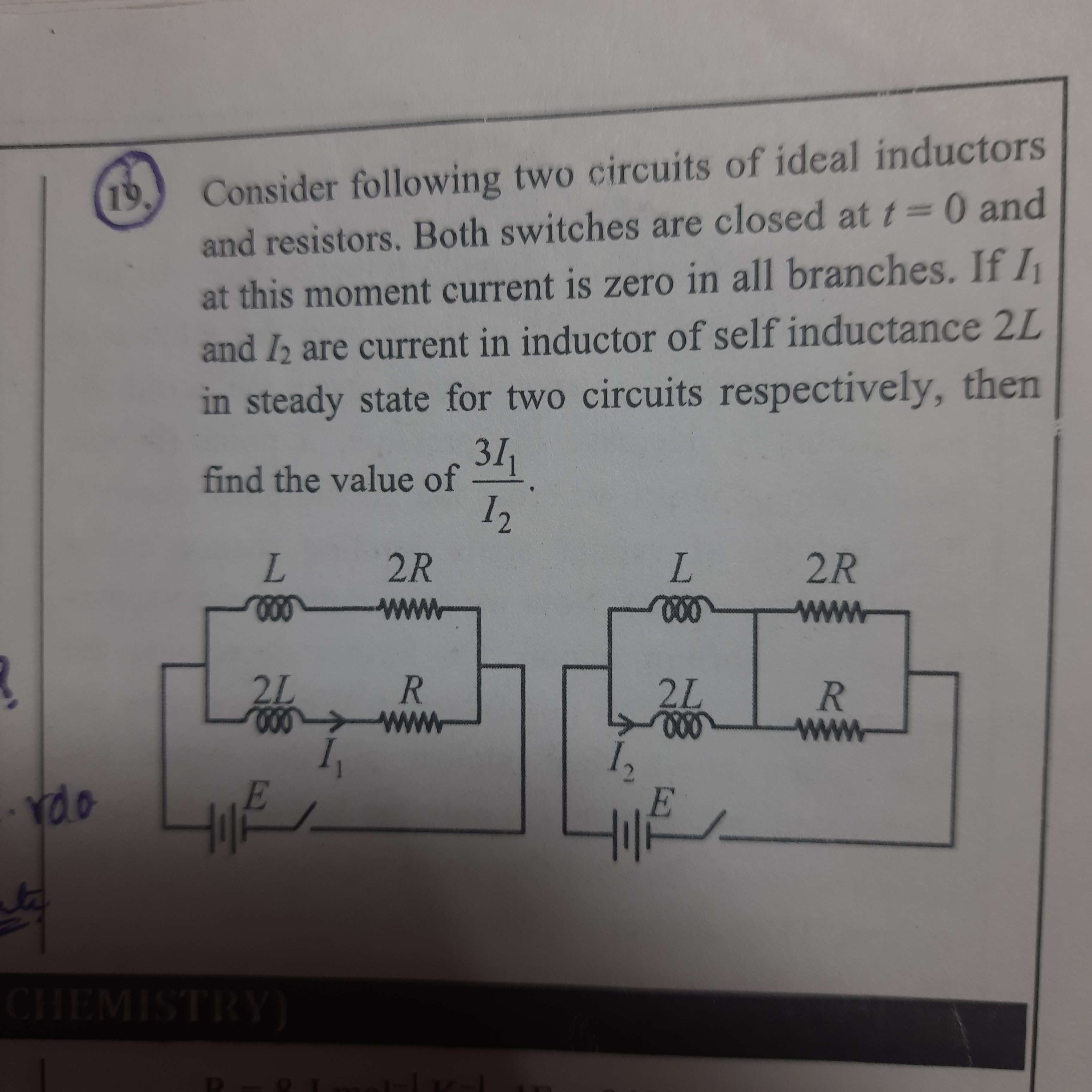
current in inductor pucha hai na
I1 i2 hi hai vo to
sun toh le
pehle circuit mein final state pe total current nikal
upar aur neeche
current bhejde
L1 i1 = L2i2 hoga
i1 + i2 = obatined current
(diff from ques wala i1 i2
How's this related to AC?
(I might have quit physics too long so I'm sorry. Was just lurkin'.)
it isnt
Inductor dikh jaye ac likhdeta hu main chahe hai nahi
Ah. Then replace inductors by pure wires and solve it that way?
In first one effective resistance is 2R/3, in the second one it's 2R/3 :/
Ah, I_1 is the current in that branch
Bhai par isse bhi current to same hi ayega na branch mein
Okay, so call 3V/2R as V' then I_1 is V'/R while I_2 is V'/2
Idts, because dono inductors ke across same p.d. hai
So L1 d(i1)/dt=L2 d(i2)/dt hoga (jahan d1 and d2 are currents passing through those inductors)
Are han
Toh irrespective of time current passing through them ka ratio is fixed.
In l1 i1=l2 i2 as mentioned above
thing is he needs current in inductors in diff circuits
We have determined I1 to be V'/3
Now we know the net current flowing in the second one is V'
So since the ratio of current of inductors is 2:1, current gets split into V'/3 and 2V'/3.
So the required ratio is (2V'/3)/(V'/3)
Which is 2.
And the answer is 6.
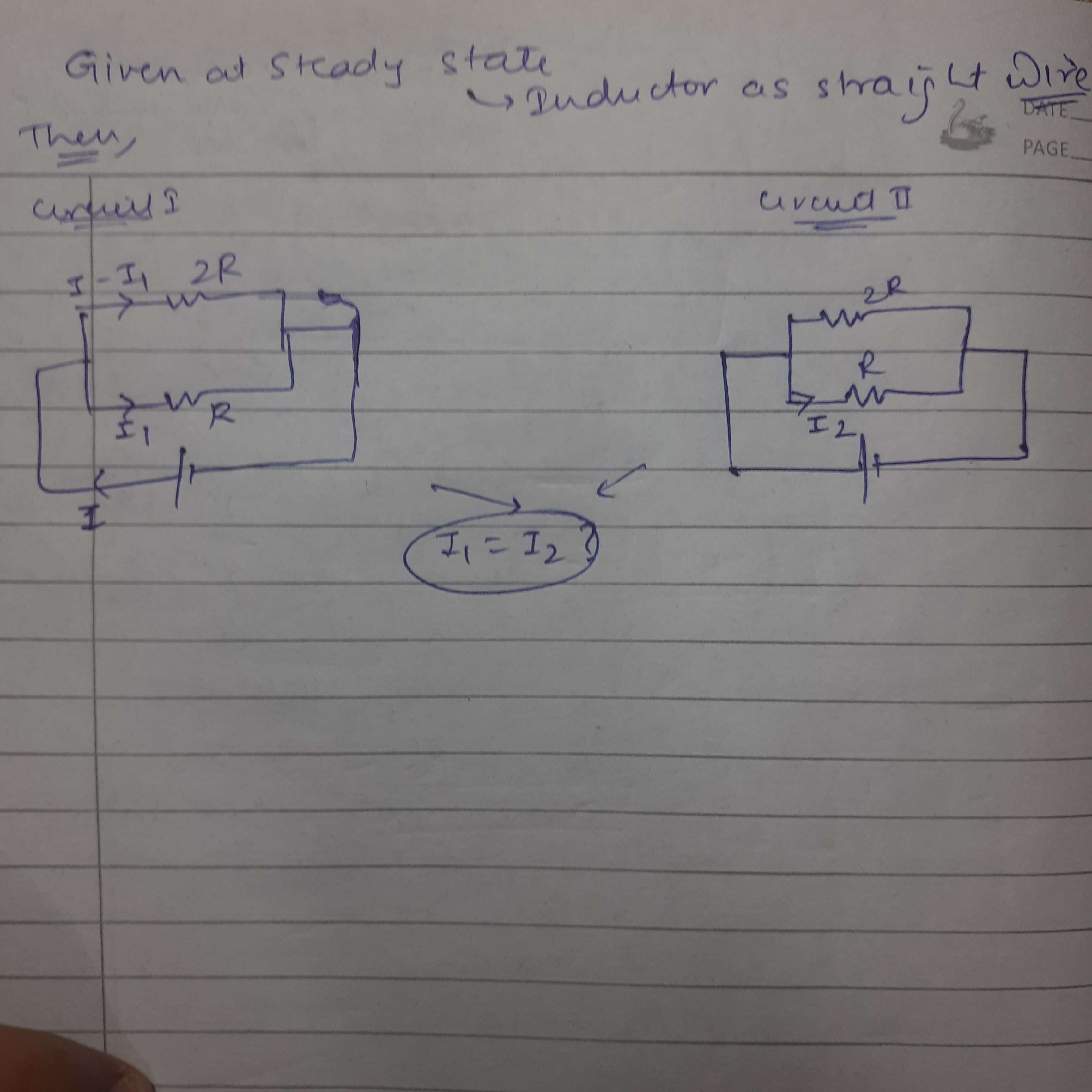
Circuit on the left
Some class illustration
Right vale circuit ka bhi bhejio zara
Agar likha ha
trying to figure out
for second steady state hai toh inductor hata ke eq resistance nikal kar i aagya phir uska current distribution which is inverse of L se nikal kar karne me galat hoga?
left ka yeh shi hai ?
Haan yahi aya ha mera bhi
inverse kaise
acha
han
yeah me too
but fir toh right left same ho jayenge
@SirLancelotDuLac can you explain once again what did you do
sahi baat hai
@integralofe^2v
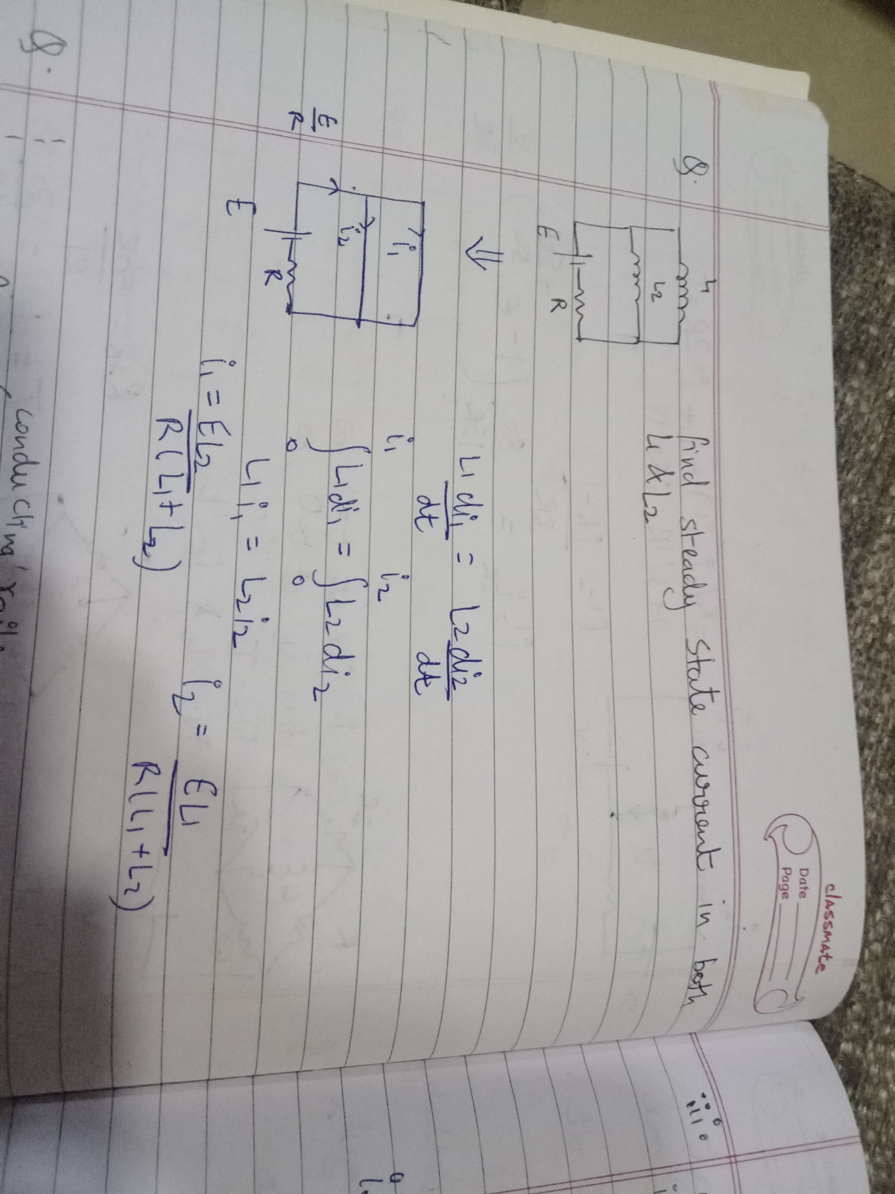
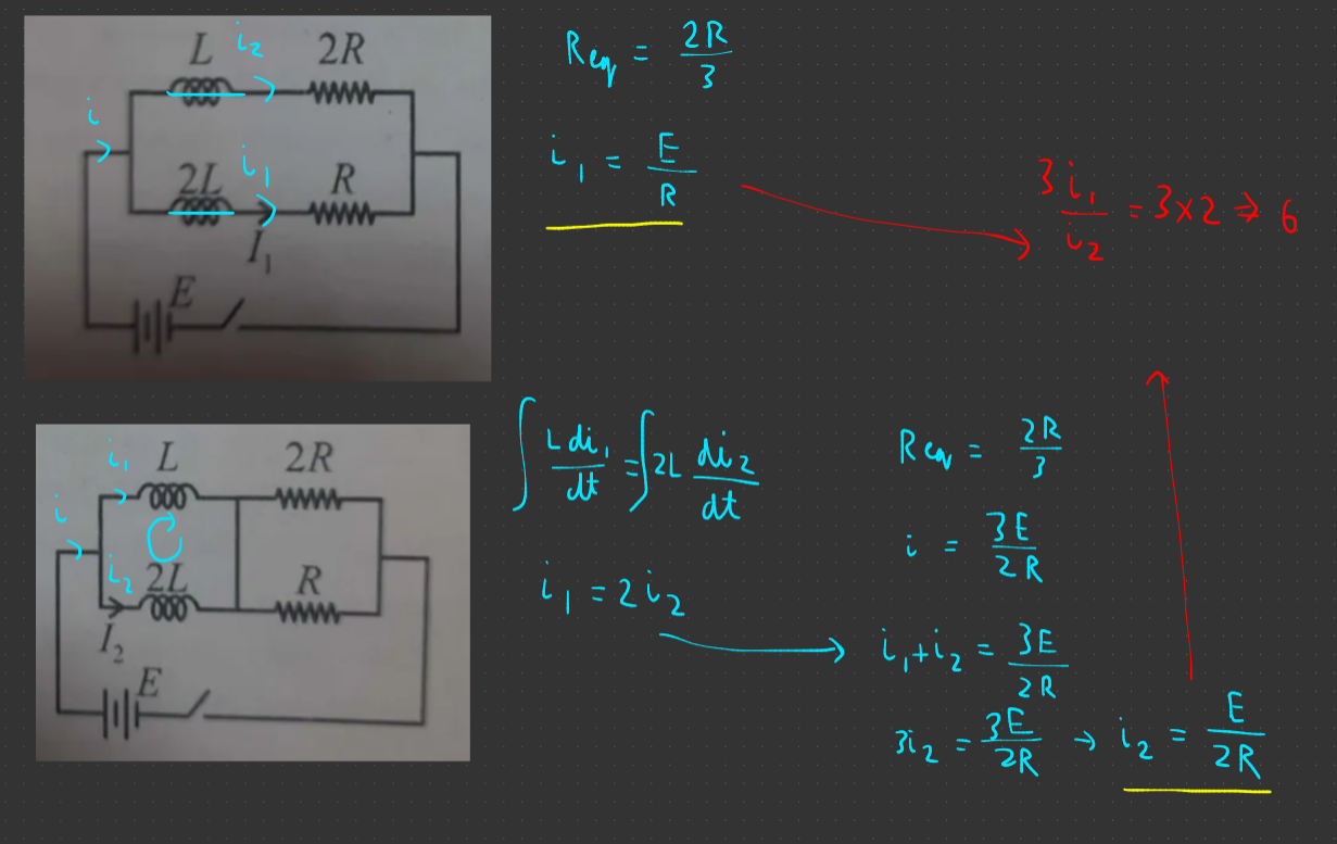
take kvl in the inner loop of inductors
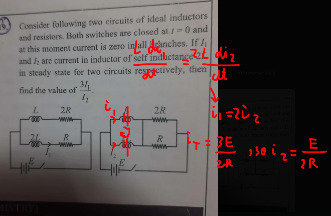
u can get a relation between i1 and i2 in right wala circuit after integrating, and yk the eq resistance so u cn find total current then divide it in i1 and i2
for left wala circuit just assume inductors to be straight wire nd find current from there
Look at this
3 possibilites
1. U r wrong
2 . I am wrong
3. Book is wrong (ans is 6)
yar vahi to karra ha
Isnt this same as mine😭
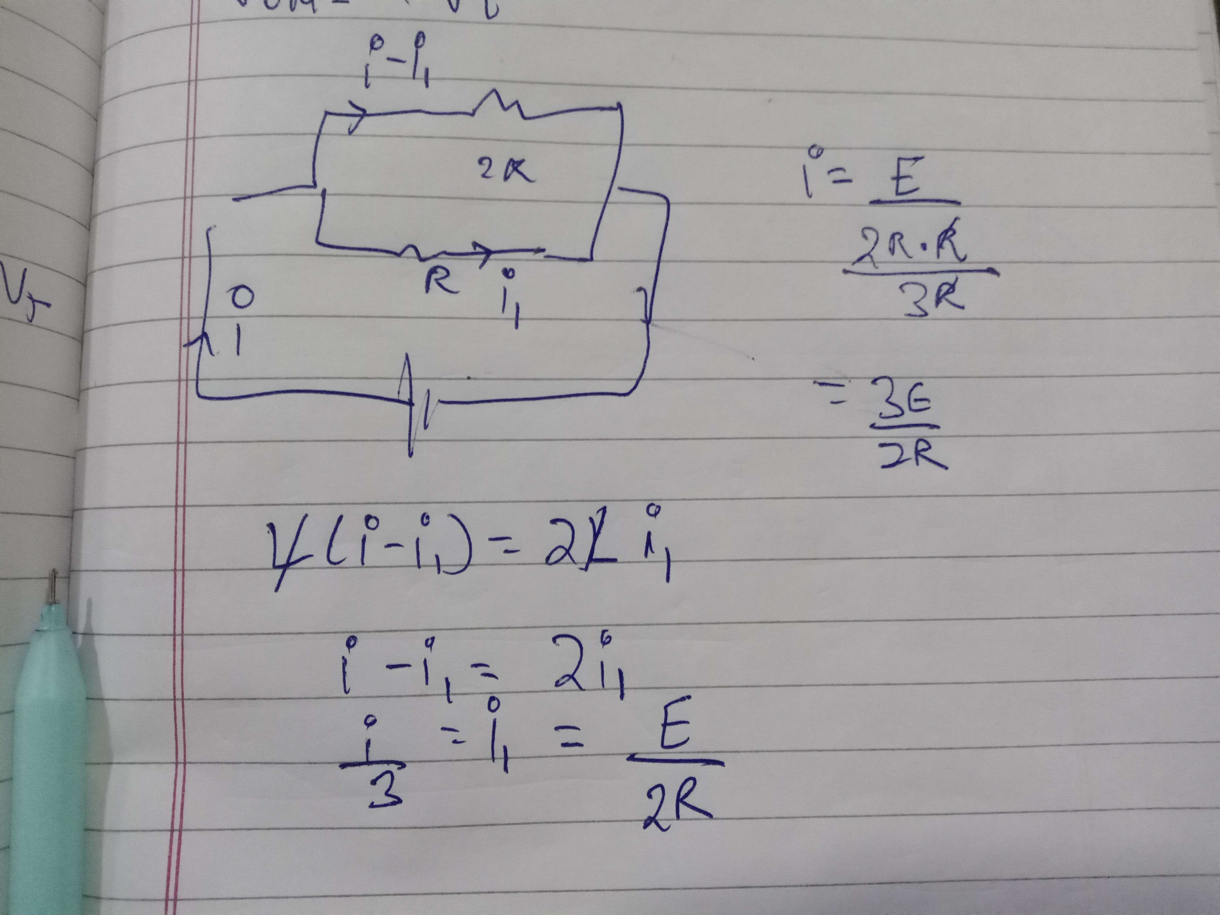
The current i1 from circuit 1 would just be E/R so 3 * E/R ÷ E/2R is just 6
i1 = E/2R
How did u even write tht kvl equation, tht dosent seem right theres inductors and resistors both, but if u consider inductor as straight wire at steady state current would just be E/R
R(i1)=2R(i-i1)
look at this
Yea here i see in the upper loop only 2 inductoes are there so u can apply kvl but in this que in the uppet loop theres inductors and resistors Both which u didnt conside, u can dk this in circuit 2 which i did in upper left loop where there r only 2 inductors
okkk
makes sense
@integralofe^2v kya ek baar pura solution likhke bhej doge?
sure basically in first circuit treat inductors as normal wires and in 2nd circuit use loop law
Also, do we neglect the internal resistance of inductors?
Yea
Alright thanx, i will close this shortly