Hi Walmis, After the order is placed how long will it take to ship the VPforce RHINO FFB base?
Hi Walmis, After the order is placed how long will it take to ship the VPforce RHINO FFB base?
 B
B B
B A
A K
K SSKKKKSKS
 NNKKNNKKKN
 W
W WW
WW A
A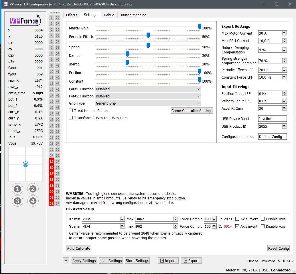 KKWWW
KKWWW G
G J
J O
O R
R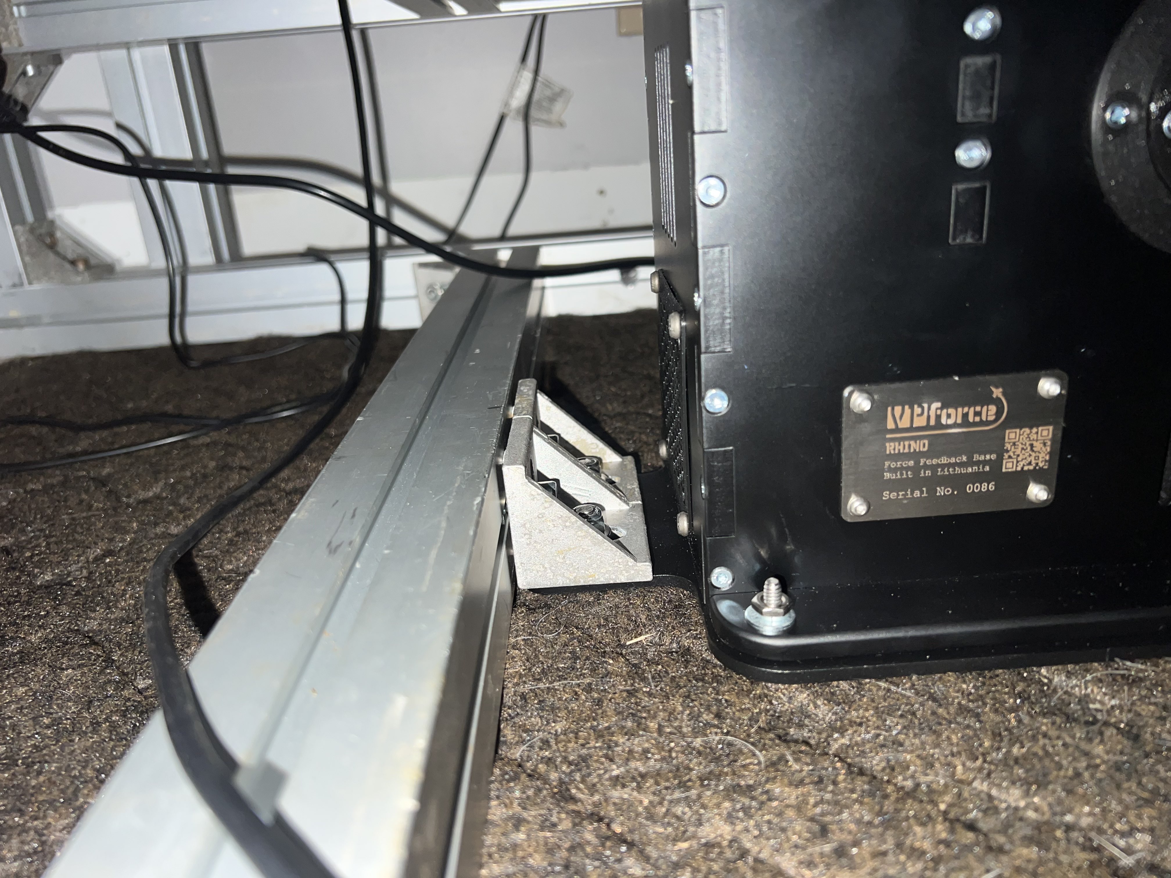 KKO
KKO ZZ
ZZ
 TZZZ
TZZZ GNN
GNN T
T T
T


