probably your speaker, Arduino `tone` goes down to 31Hz as i recall
probably your speaker, Arduino
tone goes down to 31Hz as i recalltone goes down to 31Hz as i recall
tone D
D C
C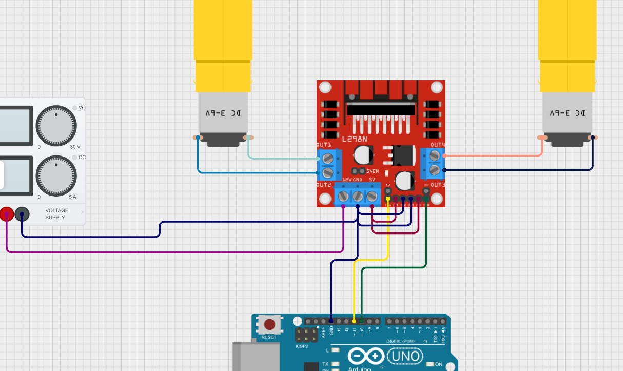
 AC
AC TCTTCTC
280 Micro DC Motors is the item description.TCTTTCT II
II WTT
WTT D
D D
D D
D AATATTA
 maybe I should try selecting another version other than latest?TTTA
 A
A
 thank youT
 thank vss its his tests and shared data. I just have it saved.
 TTT
TTT
280 Micro DC Motors
