
 S
SYa, I didn't realize it had one now I'll prob switch. I feel like I need to cold-start DCS at this point with all the shit to run all the shit I use 
 D
Doh, I hear ya 
 K
Kis there a new telem version? latest version I see is dated March 19th...

 T
TI am sure it is a wiring issue in the extension as when the cable is stretched straight out behavior is okay, only when compressed that I get the errant button behavior. Ordered another one this morning, and can meanwhile manage with the stick with the solid button 1 and the apache, the force trim effect being the main reason to buy the rhino in the first place.
 W
W@Rhino Owner @FFB/Kit Owner I've pushed a firmware update today. Fixed some quirks and the
@.durham Try it out, maybe it will help with the issue you're having.
Force Compensation function should work properly now when axis is scaled.@.durham Try it out, maybe it will help with the issue you're having.
 R
RWith the travel limiter that can be 3D printed. Do any of you have a source for the total travel or deflection for a uh-60, ec145, 64c etc. looking for a good approximate number so I can print one limiter plate.

 I
IWhat does force compensation do? A quick look through the manual I don’t see it on there.

 J
JThe gimbal only has a finite amount of stiffness. At full force and full deflection, the gimbal will eat some of the travel, such that the motor won't see the full deflection but only a certain fraction.
At least this is what I understood it does.
At least this is what I understood it does.
 S
Sso far, disabling vjoy seems to have fixed it- ill have to fully migrate away from it now!
 R
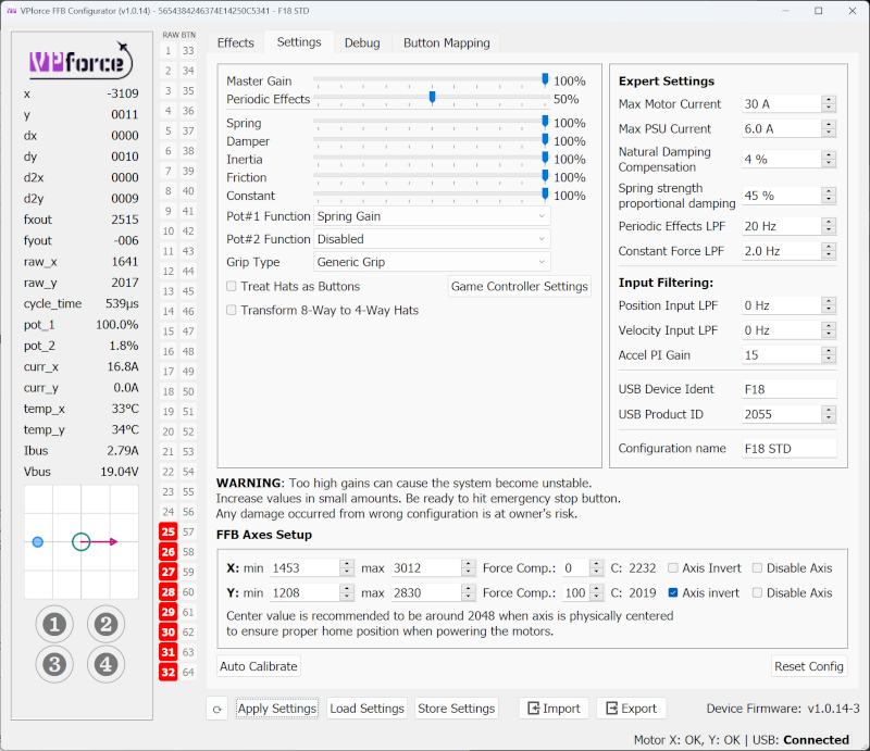
R@walmis After applying the new firmware update I'm seeing some odd behaviour with force comp on the X axis. Increasing the comp is reducing the reported axis deflection rather than compensating for loss of deflection caused by the spring induced flex. Y axis comp is working correctly (although it seems to be much more effective now).
I have an 11 degree throw limiter installed and axis have been calibrated with it.
I have an 11 degree throw limiter installed and axis have been calibrated with it.
 I
ICan you explain where this setting is? I don’t see it
Invm i found it.
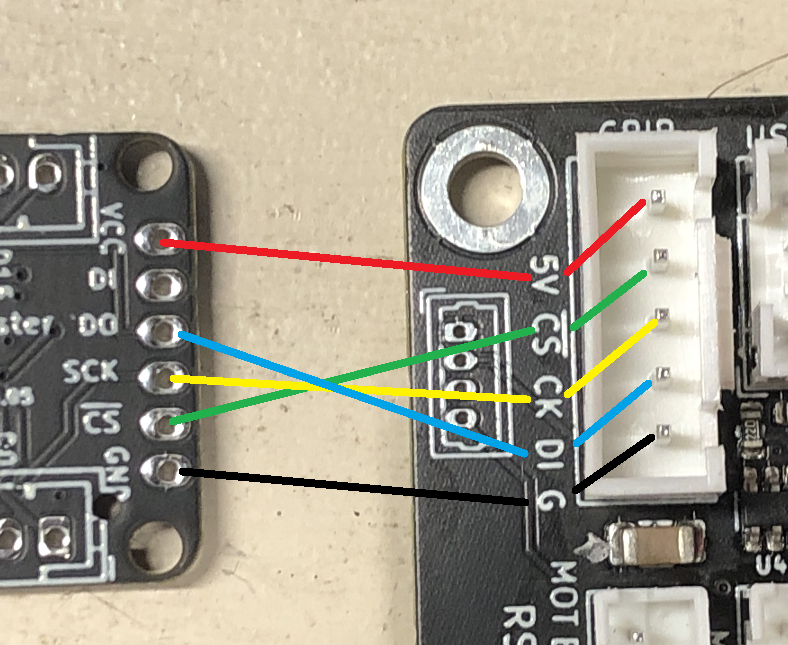
SJust to make sure before i wire this up, is this the correct order? match pin names except Shift Register Do -> Main board Di, and Di on shift register not used?
 S
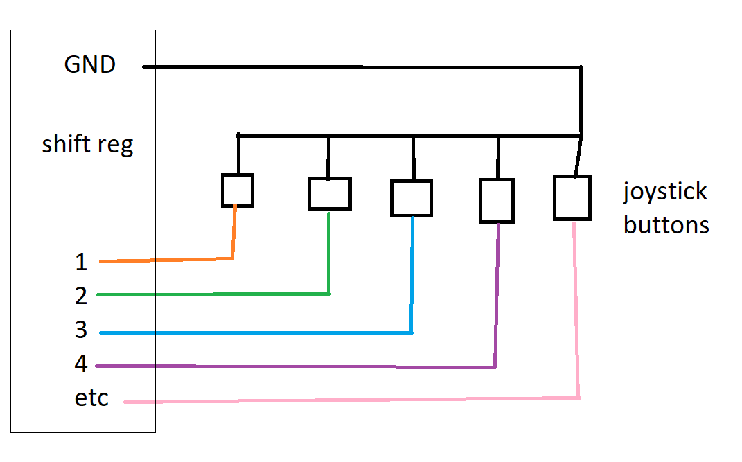
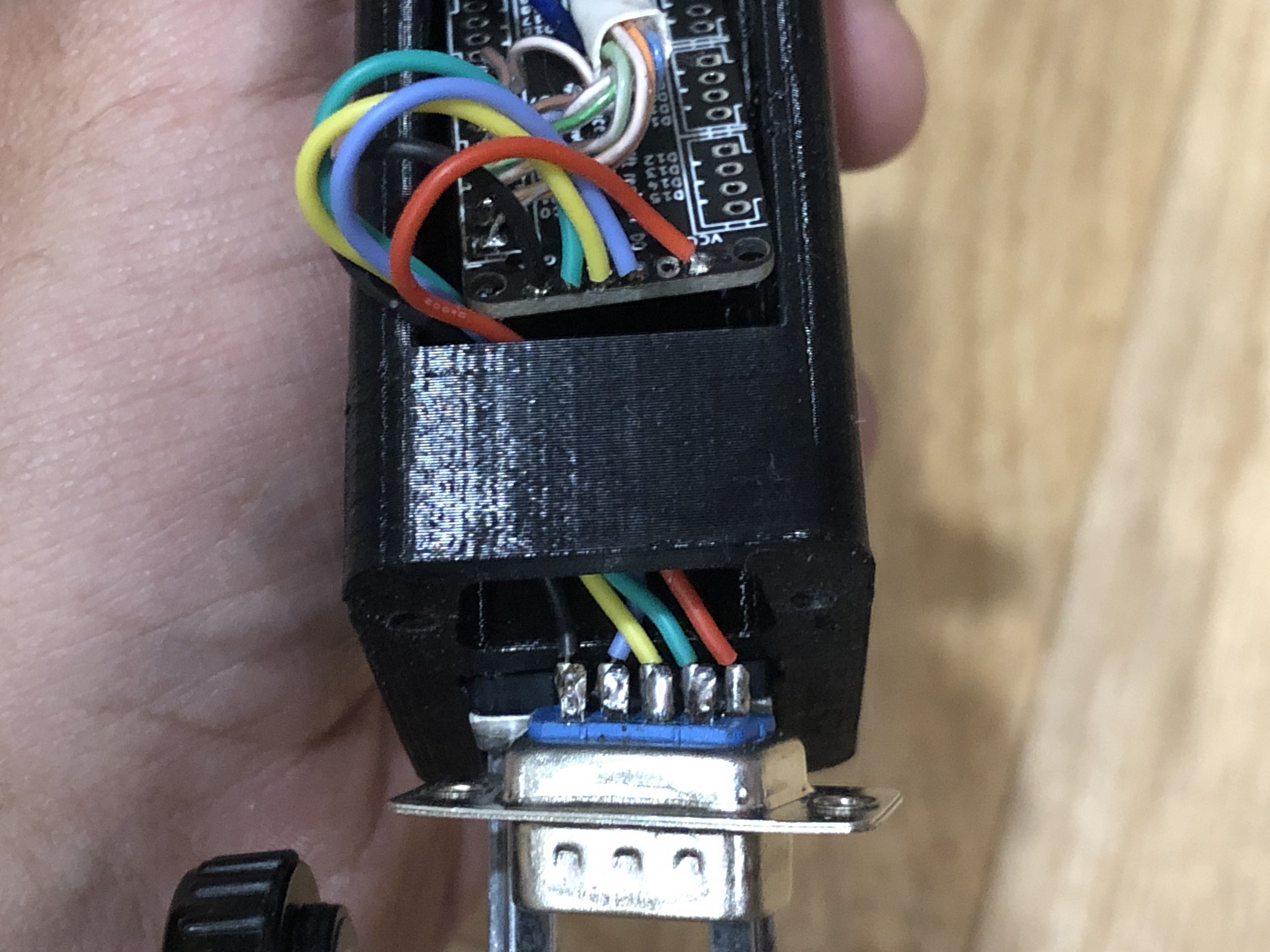
Sand then the joystick like this?
 W
WThanks I'll check this first thing and push another update 
 W
WYes, these are exactly correct
 W
WVjoy gave me nojoy. I uninstalled it also.
WShould be fixed in v1.0.14-5
RFixed! Thanks 

 T
TThis is concerning for me. As I rely on joystick gremlin and hid hide. I hope I can make it work.
TSurely many Rhino and kit owners are using vjoy/gremlin. I wonder why it’s been a problem for you guys.

 P
PI've used the Rhino with HID Hide a few times so far I've had no trouble, using a vkb grip & the VPforce Loopback app plus hid hide to make IL2 see the Rhino & grip as one & not see the vkb grip alone.
 T
TGlad to hear it doesn’t sound like HID hide is the issue. But I use Gremlin/vJoy to merge the throttle and clutch on my sim racing pedals into a single axis for rudder pedals in flight sims. So I need to keep it enabled.
Ptime to invest in separate rudder pedals?  Even just the 'cheap' Logitech ones will do, their what I use, plus light & easy to move, I have my logitech racing pedals mounted inverted above my rudder pedals & they both fit
Even just the 'cheap' Logitech ones will do, their what I use, plus light & easy to move, I have my logitech racing pedals mounted inverted above my rudder pedals & they both fitTI saw in the previous discussion with @smitty981 it was maybe xpforce related? I don’t have plans to use XPForce so if that’s really the issue then it’s no big deal.
TSmitty, did you try it at all with vJoy enabled, without XPForce?
 A
AI use vjoy and joystick gremlin and have no issues? I made a custom plugin to do differential braking with the lever on my joystick grip combined with my rudder pedals
 T
TThanks, I figured there had to be more experiences. Glad to hear it’s worked for you!
TI’m down to the point of printing my pulleys and then sourcing belts for my kit build. I am getting antsy to try it out!
SIt works as a joystick without xpforce but what’s the fun in that? 
 H
HWith latest IL2 patch, the Y axis spring force seems gone... anyone having same issue?
 R
RYep that’s what I’m experiencing
HIt must be the game... with DCS working as usual
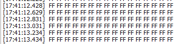
Sso i wired up as shown.. have 5v on the shift register.. and nothing. generic debug shows this
 S
S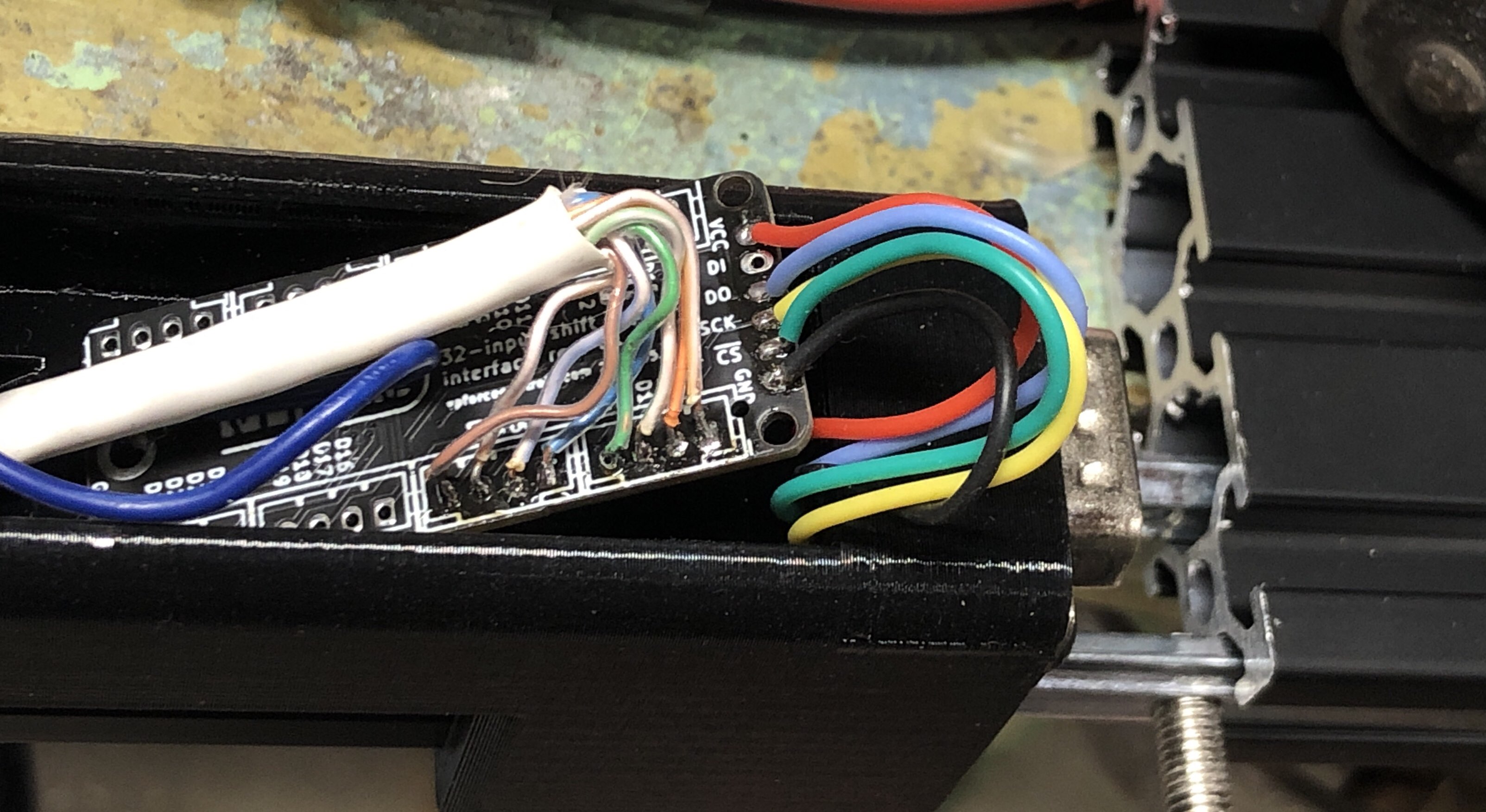 S
SAll pins connect to gnd when pressed.
 K
KIf it were me, I’d wire the shift register up to a simple arduino (uno or similar) and send the output of the shift register to serial so you can see what’s being read. There are a ton of guides on YouTube for reading out a shift register with arduino.
Sno need to make this more complicated. wouldnt i get the same FFFFFF's?
KYou seem like you’ve got it figured out on your own. I’ll let you diagnose
Sall the FF FF FF's are coming in even with the shift register disconnected... so even if i had a spare arduino around it wouldnt tell me much. also tried new FW update, same.
TEach FF is a hexadecimal 8 bit number (FF = 11111111) to indicate signal from the shift register board. An unpressed shift register should read:
FF FF FF FF 00 00 00 00 00 00 00 00 00 00 00 00
The first 4 FFs are for the 32 buttons (4x8 bits =32). When a button is pressed you should see one of the FFs change to something like F7 (11110111) or BF (10111111). Where the 0 in the binary byte is the button being pulled to ground.
FF FF FF FF 00 00 00 00 00 00 00 00 00 00 00 00
The first 4 FFs are for the 32 buttons (4x8 bits =32). When a button is pressed you should see one of the FFs change to something like F7 (11110111) or BF (10111111). Where the 0 in the binary byte is the button being pulled to ground.
TI’m trying to think of why you would be getting FF for all 16 bytes though. That is odd. My first guess would be an issue with your SCK or CS wiring/connections.
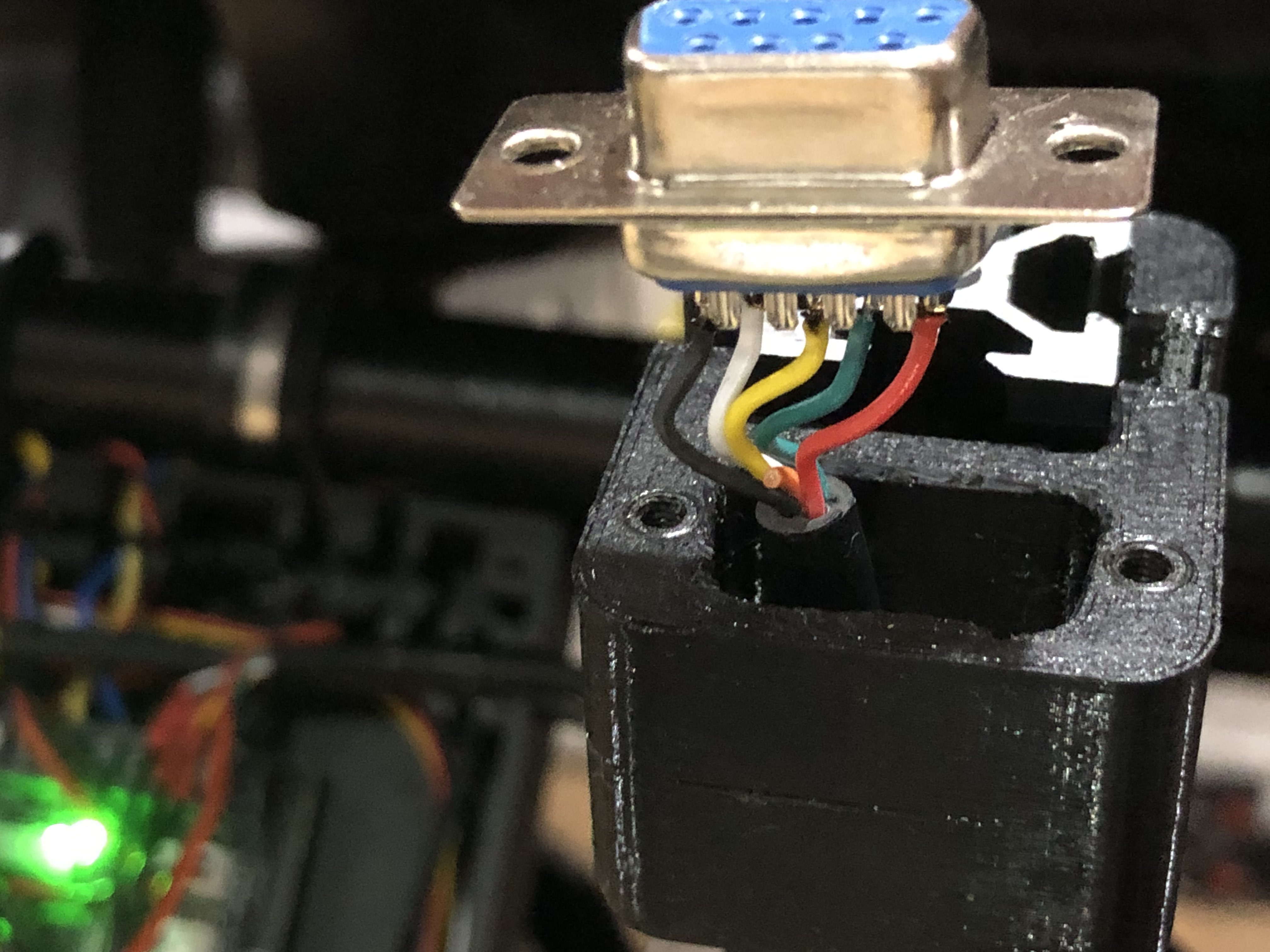
SThat’s what I don’t get.. I followed my pic above exactly .. I did the crisscross in the joystick, and then it’s red, green, yellow, blue (white on the lower cable), black.
 S
SNo shorts anywhere either.
TAnd you’re certain the 9 pin plug isn’t the issue? I agree at first glance it looks correct. I would unplug the JST XH 5pin from the main board and check continuity between the SR and JST plug. You could also make sure there is nothing shorted together too for good measure.
Syep i checked for shorts, all good there. all the button pins beep on the meter for continuity when i press the corresponding button. ill check continuity with the 5pin to register board, ive been using this 9pin in this application before with no issues and the female one is brand new
Severything is good thru the 9pin
TEven with nothing connected to the shift register button wise you should see the debug as FF FF FF FF 00 00 00… so to see all 16 FFs to me says it is an issue between the SR and main board.
Sif i yank the 5pin i get all FF FF
TSo with nothing plugged into the grip plug it’s the same as with the SR plugged in?