my belt got loose so I tighten it up but I was a dummy and didn't hit the E stop before taking belt off so now I had to re calibrate every single profile I had... I see this number is now RED is this a bad thing?
Red number means you have a calibration value outside 0..4096. If you turned on your base with the stick in the negative X region it would not find proper center and would lock itself to one side. To fix it you would need to take the belt off, manually set the calibration range 0..4096, then put the belt back on with your stick centered.
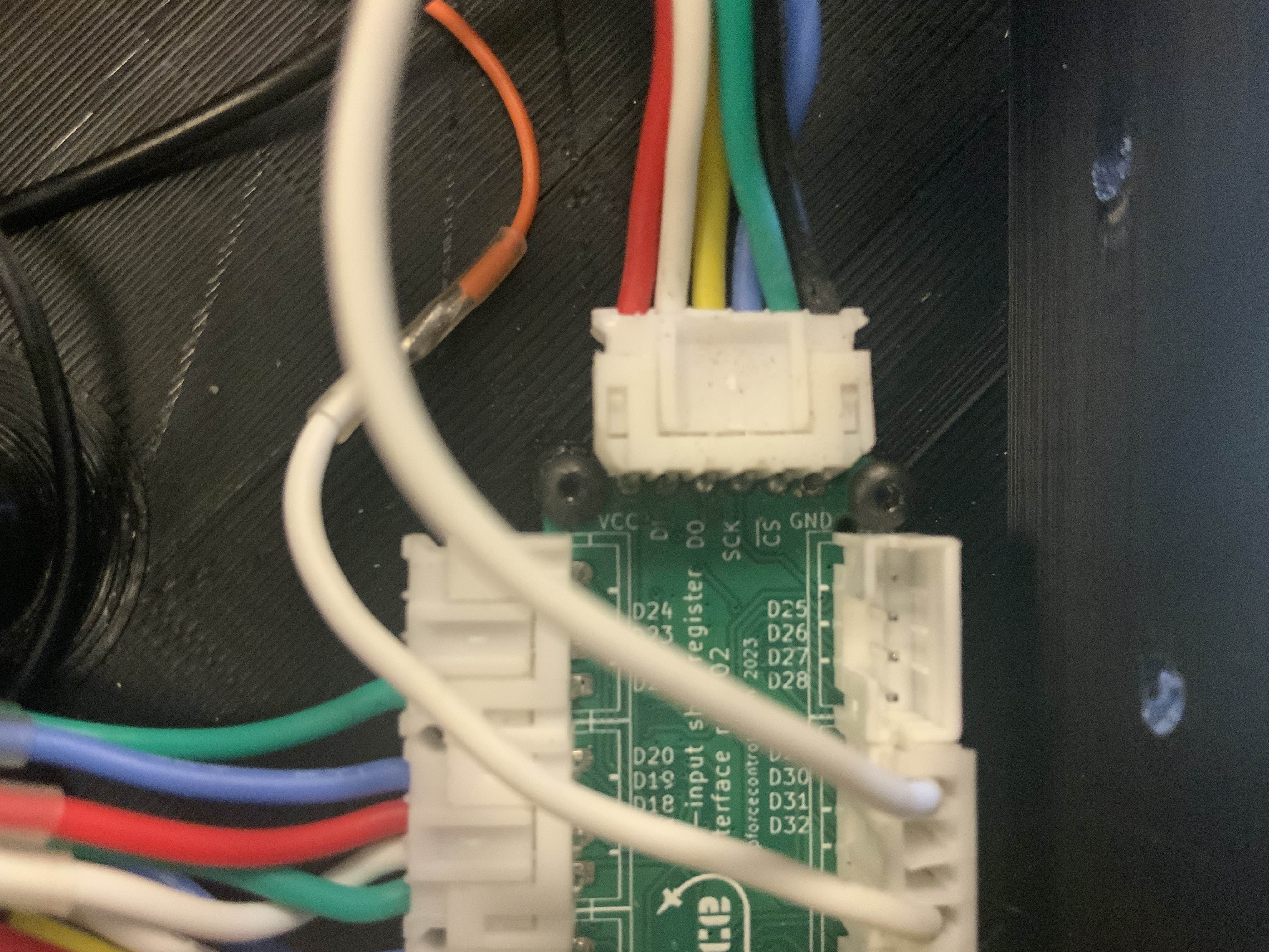
Thanks…..I guess I need to check the wiring again……none show up, indicating a ground issue but I’ve checked continuity and it’s fine……mmmmm I wired it up as per pic attached. Selected VP shift register as the grip selection……switches to ground on Shift register and to each of the 32 input positions, but nothing …….is there something else I have to enable?
Button wiring is the issue. Each of those 4 pins are buttons. They connect to the ground from the VPF main board. So in your pic you have yellow/yellow/yellow/black
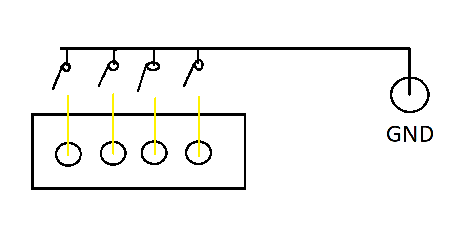
Actually as per your pic is how it’s wired…….the pic I posted was from a pic I downloaded from somewhere else on this discord to help with how the connection between shift register and VP control board. My switches are all connected to ground in series and the other side of switches to respective input on Shift register sequentially. So if there is no other requirement to do, it must be either board faulty or I’ve connected something wrong???
On the 6 pin input connector I see 5 wires which is correct but it looks like they are in positions 1-5? Hard to tell so maybe not but are you sure that is all correct? Looks like it’s missing GND but maybe that’s on the screw terminal?
Ok I see it. If the buttons are as the drawing I posted and board to board is correct it has to be an issue with the grounding or the board to board connections. This might be a dumb question but is the GND used for buttons connected to the same GND used for the board to board connection?
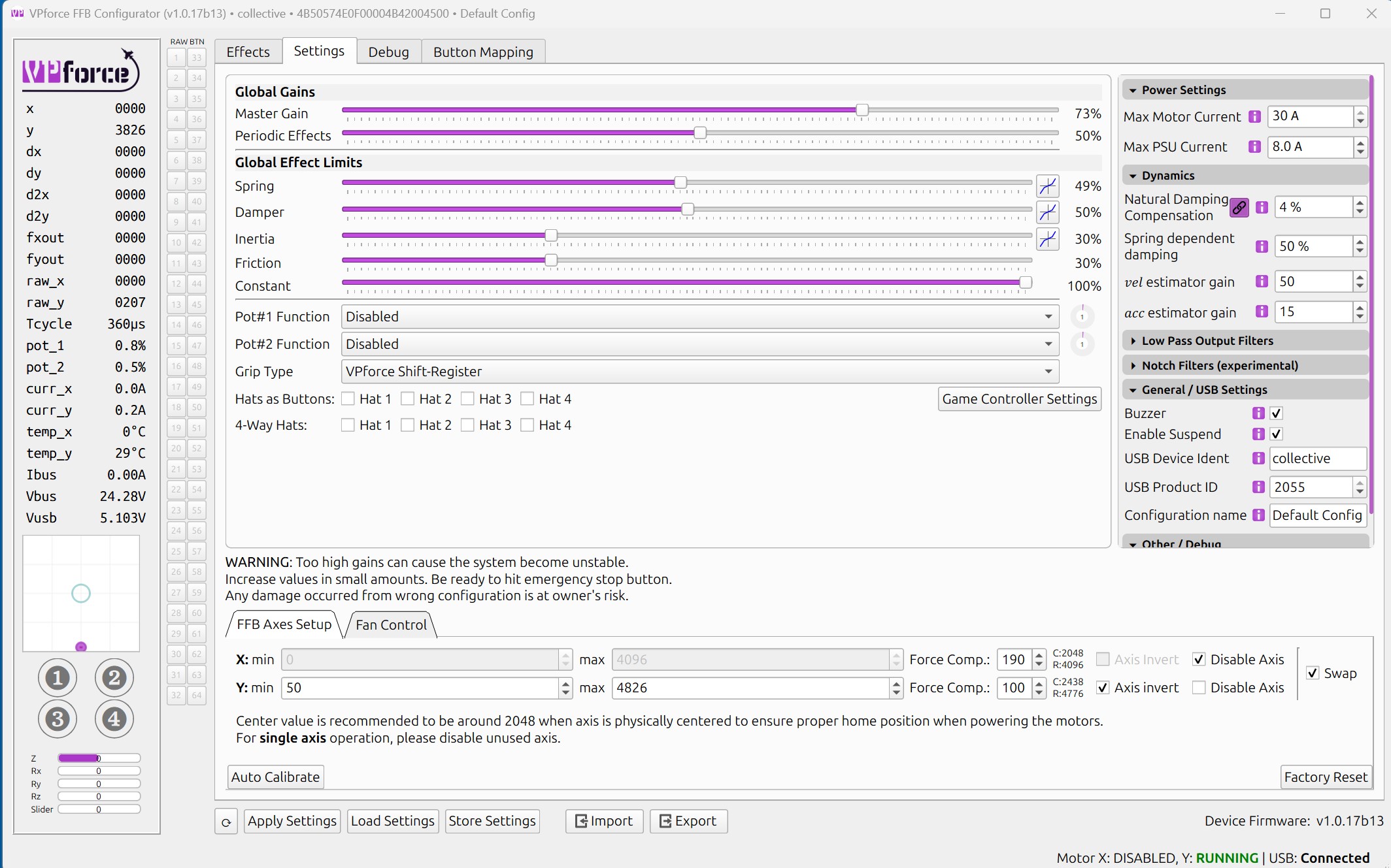
My natural damping compensation value is set at 20%, that way I feal stick moving without any resistance. Is it normal such high value providing that the default is 4%( I am using 86bl04 engines)?
hello everyone, can you confirm to me that there will be no risks, because I am about to connect my rhino VPforce for the first time, with my meanwell 360w 16A only to power my rhino for the moment? Commentaires
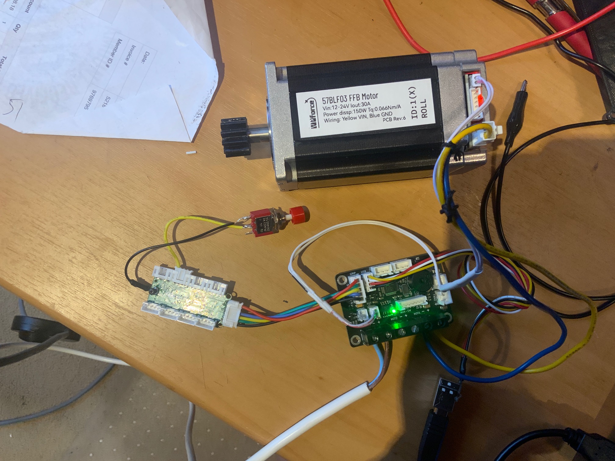
@walmis I've just ordered another pair of motors from yourselves, and a spare FFB circuit board, is it possible that you could add to the invoice and include a spare USB connector cable and PCB plug?
I have a 350w 14A meanwell with the rhino hooked up at 8amps and the rhino MFG at 4 amps, my understanding is that the device will only draw the amps it needs.
Hey Mike, I'm building a custom H135 cyclic right now and encountered the same issues. checked everything twice redid all my connection; I was able to measure 5v coming all the way through my buttons. What I didn't know; you need to apply 24v to the rhino too to have the button presses registered. I hope that fixes your problem as well!
Hi, I bought a while ago the ffb kit with usb board and couple of motors. Currently (first try) the board beeps, the led flashes once and windows states that usb board not recognized. This was kept in the ESD bag until assembled to base.
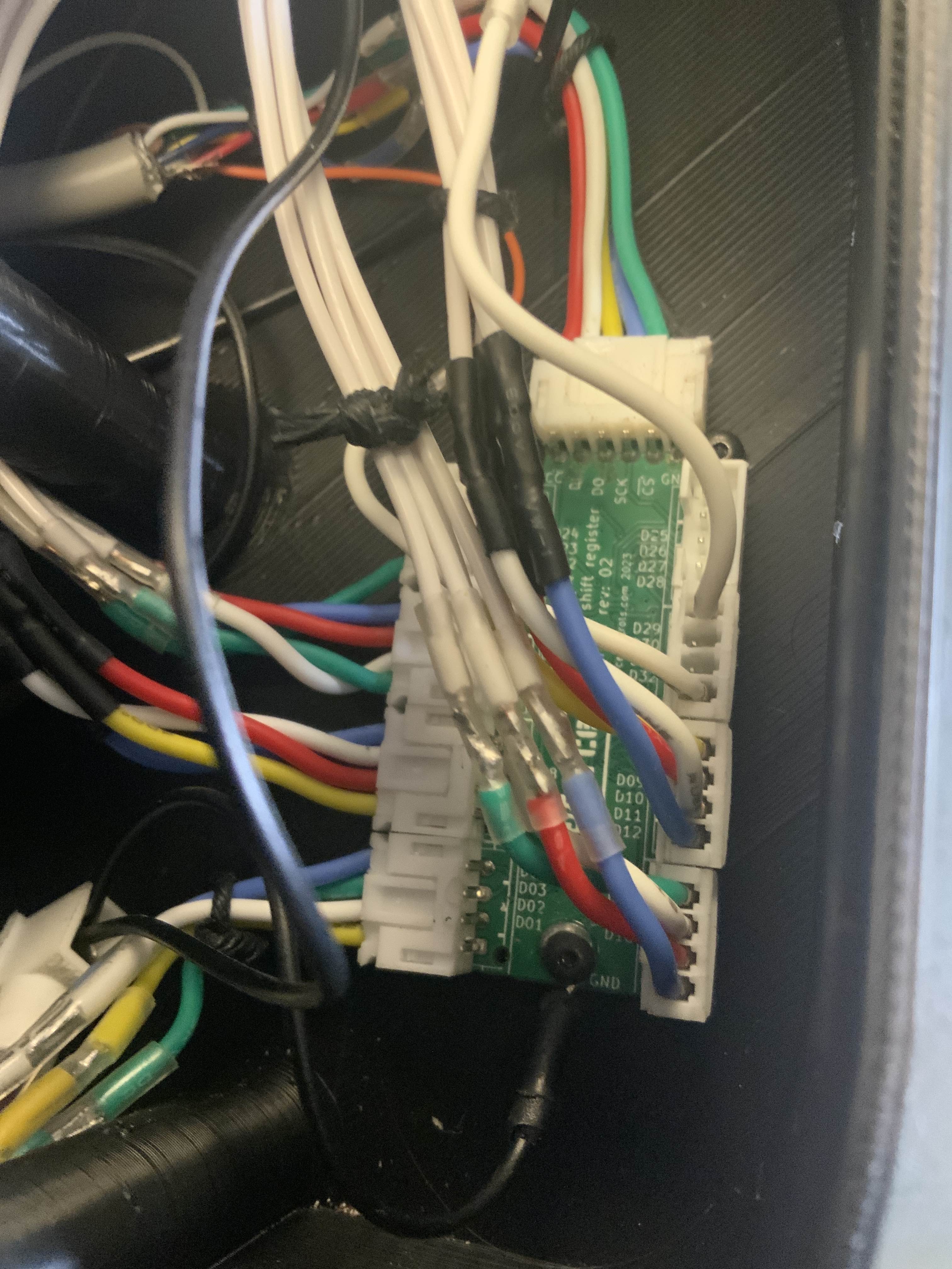
OK so I decided to take out the Shift Register and VPF main board out of my DIY collective and make up a test setup as per pic attached. This way no way there is any possible wiring issues. Just the one button to test. Nothing! no reaction to btn press.......zilch! Double checked wiring and continuity all good!
Yes tried with motor connected as well.......see attached pics.......same result, No response to button press.....ZILCH! I guess the Shift register is faulty or something fundamentally not making sense here......Unless @walmis can suggest a fix I'll have to go and try to get warranty return (new item) or look at going with a Bodnar board....which I really don't want to do as the extensive wiring has been done for the shift register....really disappointing outcome.
If you short the the DATA pin to GND on the 5 pin interface do all the buttons light up? Also you can do that test @TheAmazinGreat referenced to both boards
 T
T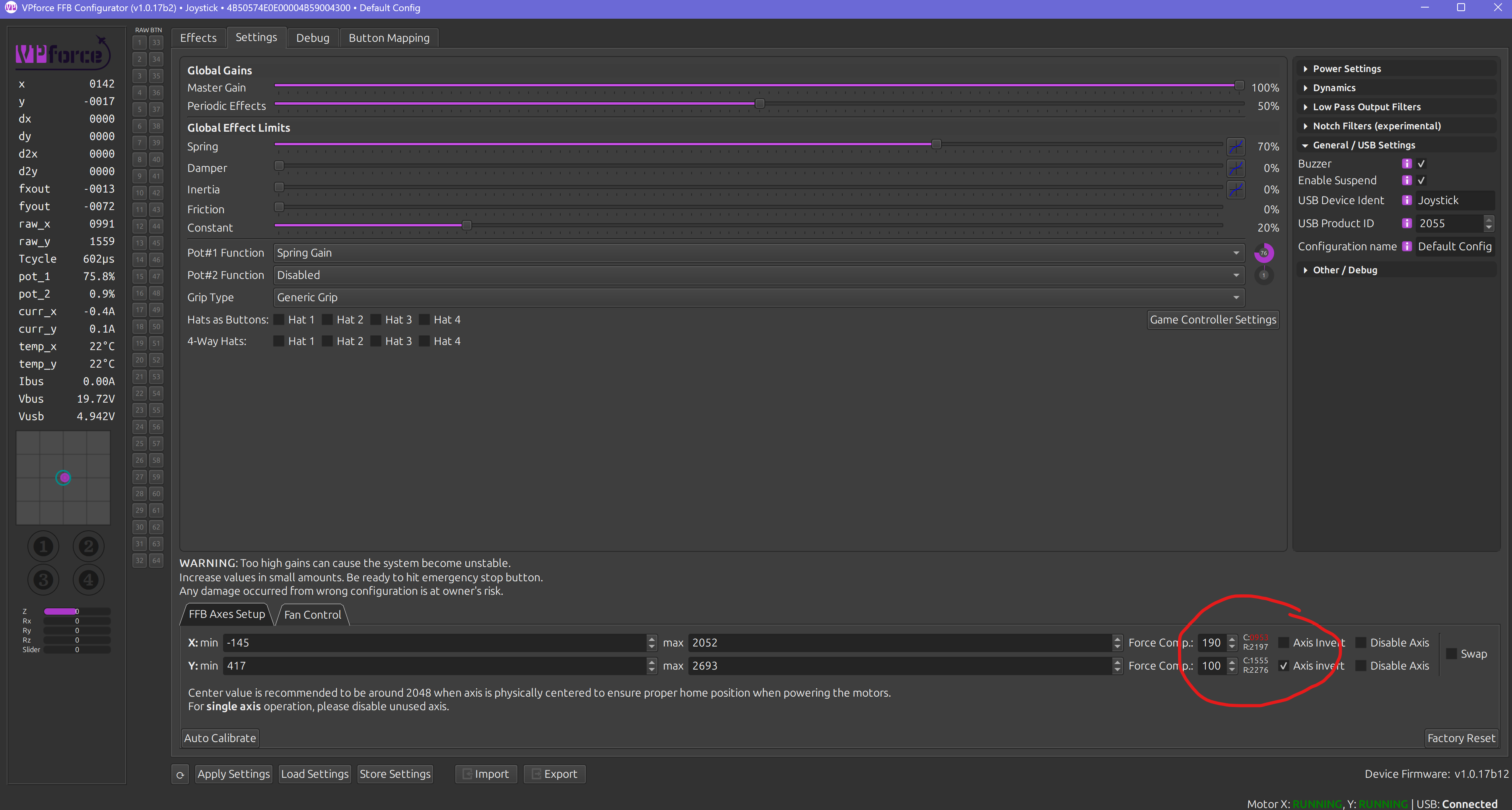
 T
T M
M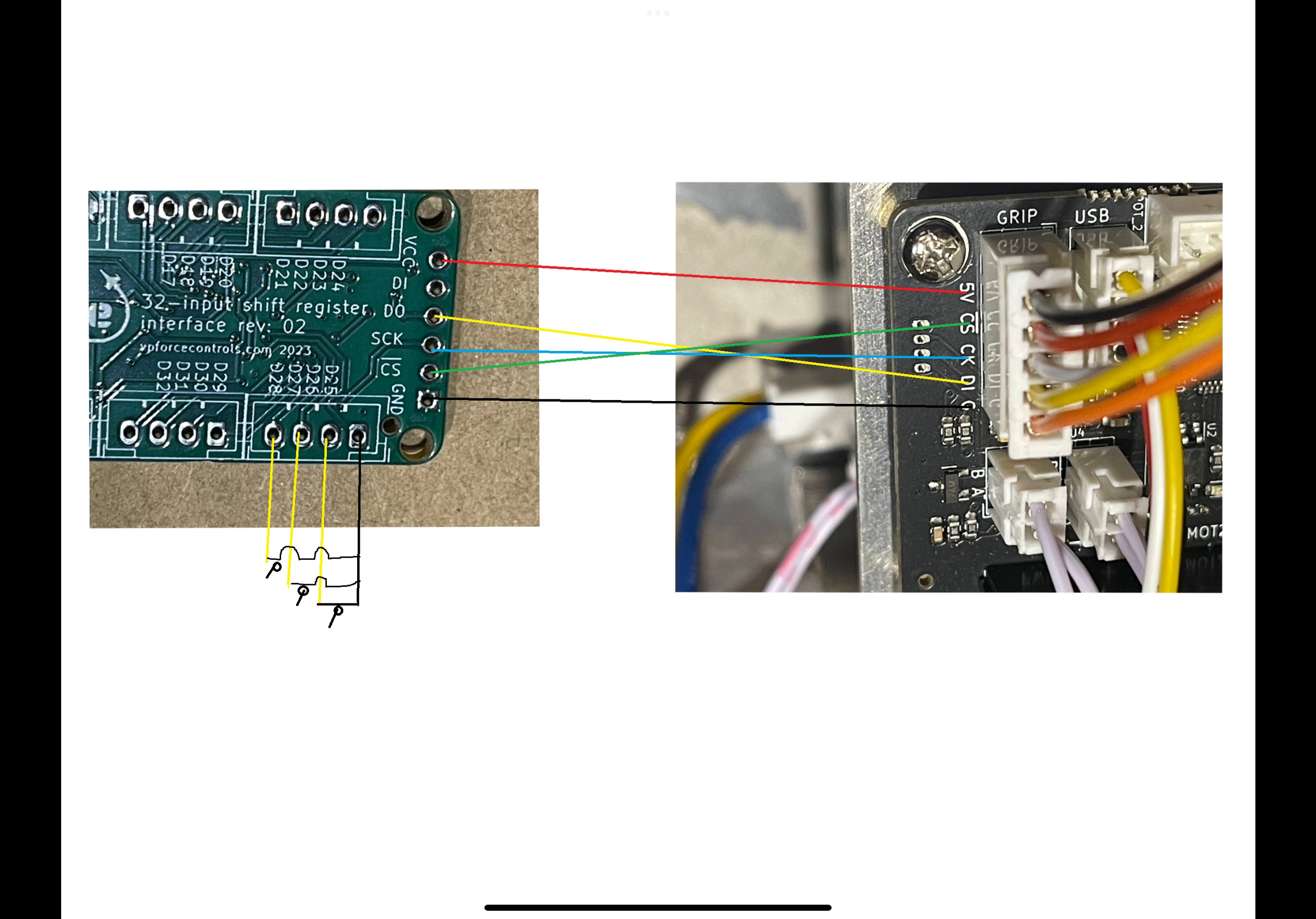
 N
N S
S
 W
W C
C G
G B
B

 F
F
 D
D C
C

 R
R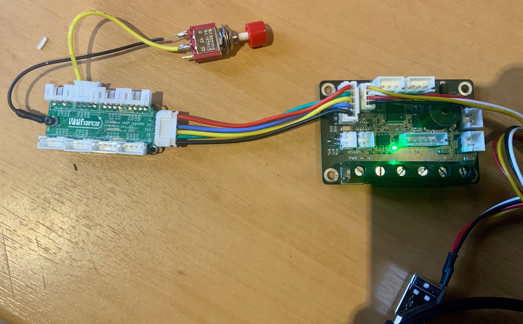

 W
W