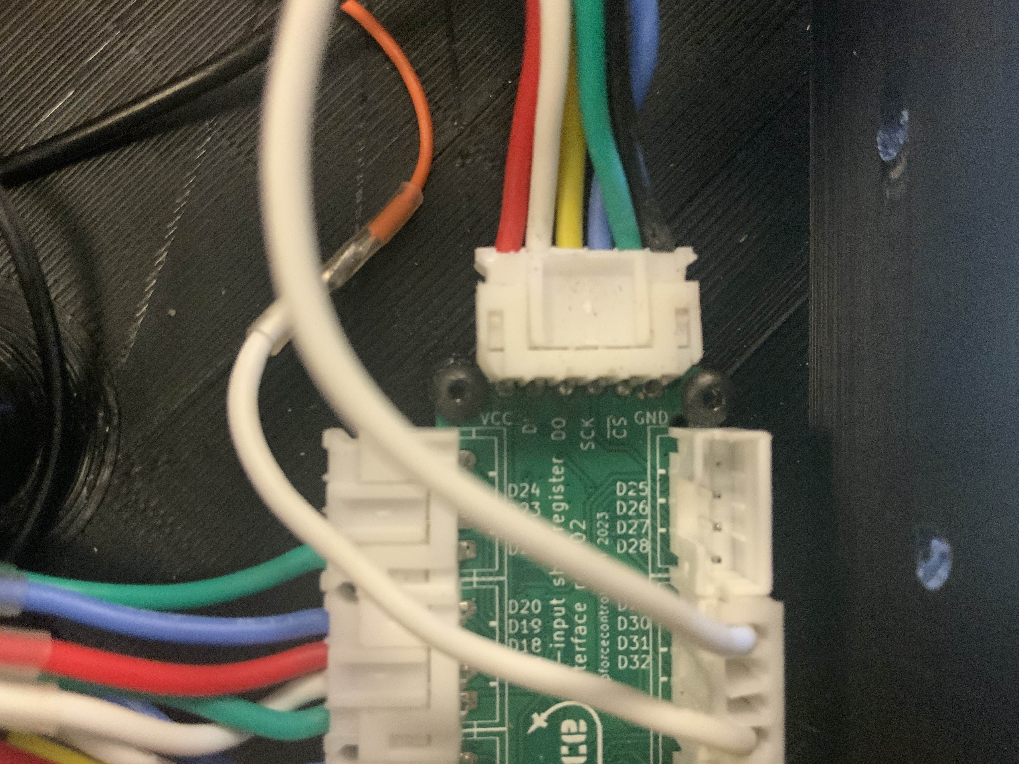
Here is a better pic……D1 is wired but goes nowhere as not used…..D0 goes to D1 on VPF board. I’ll
Here is a better pic……D1 is wired but goes nowhere as not used…..D0 goes to D1 on VPF board. I’ll recheck connection between boards again.
 TT
TT N
N SN
SN
 W
W C
C G
G BB
BB WB
WB BB
BB FTTF
FTTF F
F DD
DD C
C CCC
CCC
 R
R M
M

 M
M
 TTT
TTT WMMWW
WMMWW DDN
DDN MM
MM SDWW
SDWW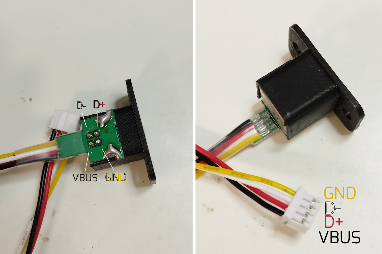 WNDWD
WNDWD