I run the z extension with the metal Alpha Prime... no issues maintaining center along with balance
I run the z extension with the metal Alpha Prime... no issues maintaining center along with balance spring and adaptive recentering
 N
N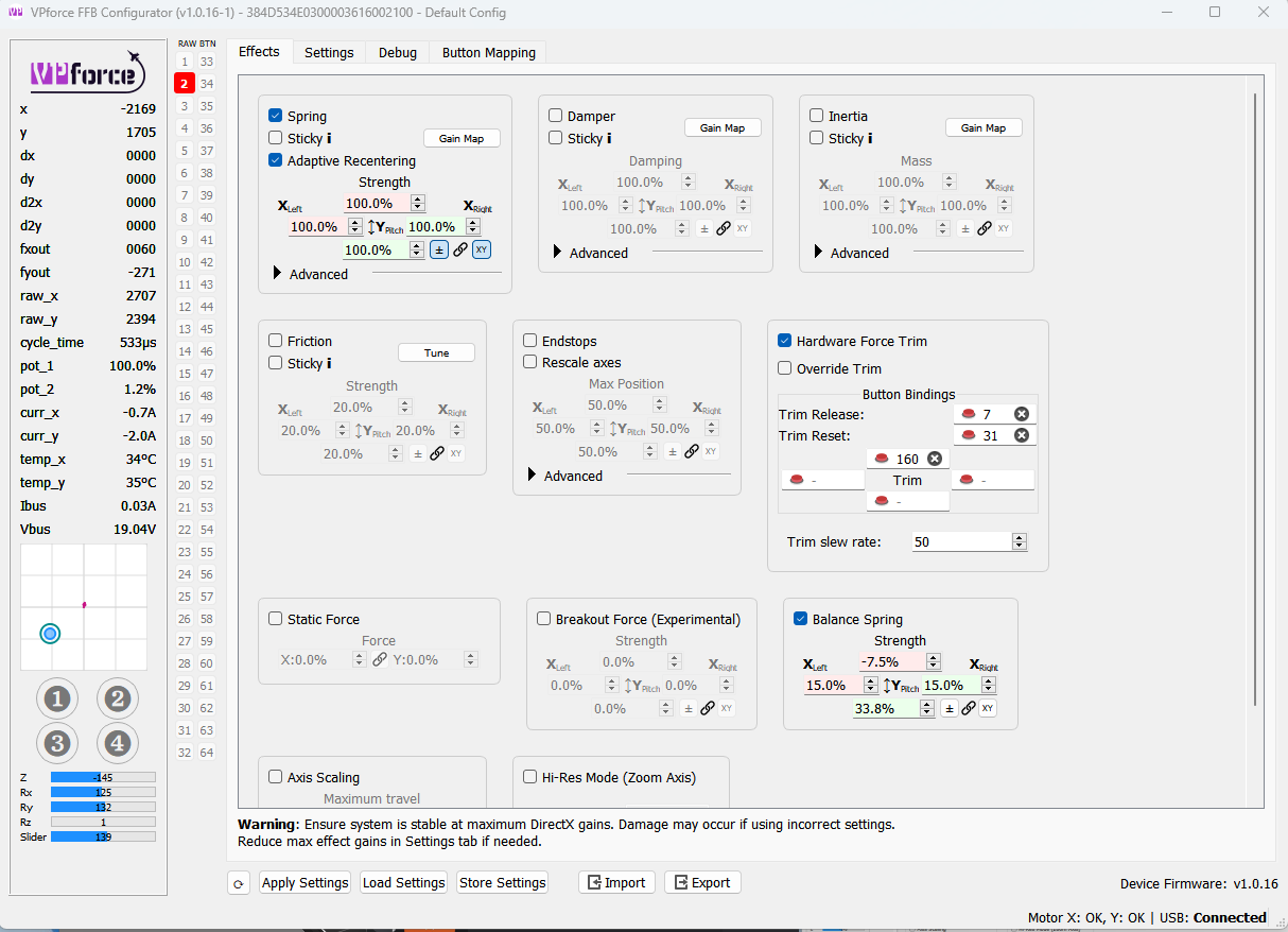
 PN
PN PNPN
PNPN ... its all sorts of wonky with weird settings and stuff from doing development.
 W
W P
P . Better I should try out by myself.P
 NP
NP . I will play with the config of DCS. THX!!!
 WW
WW WW
WW

 PWWPPP
 SSP
SSP
 M
M SPWP
SPWP B
B TTB
TTB BT
BT TBTBB
TBTBB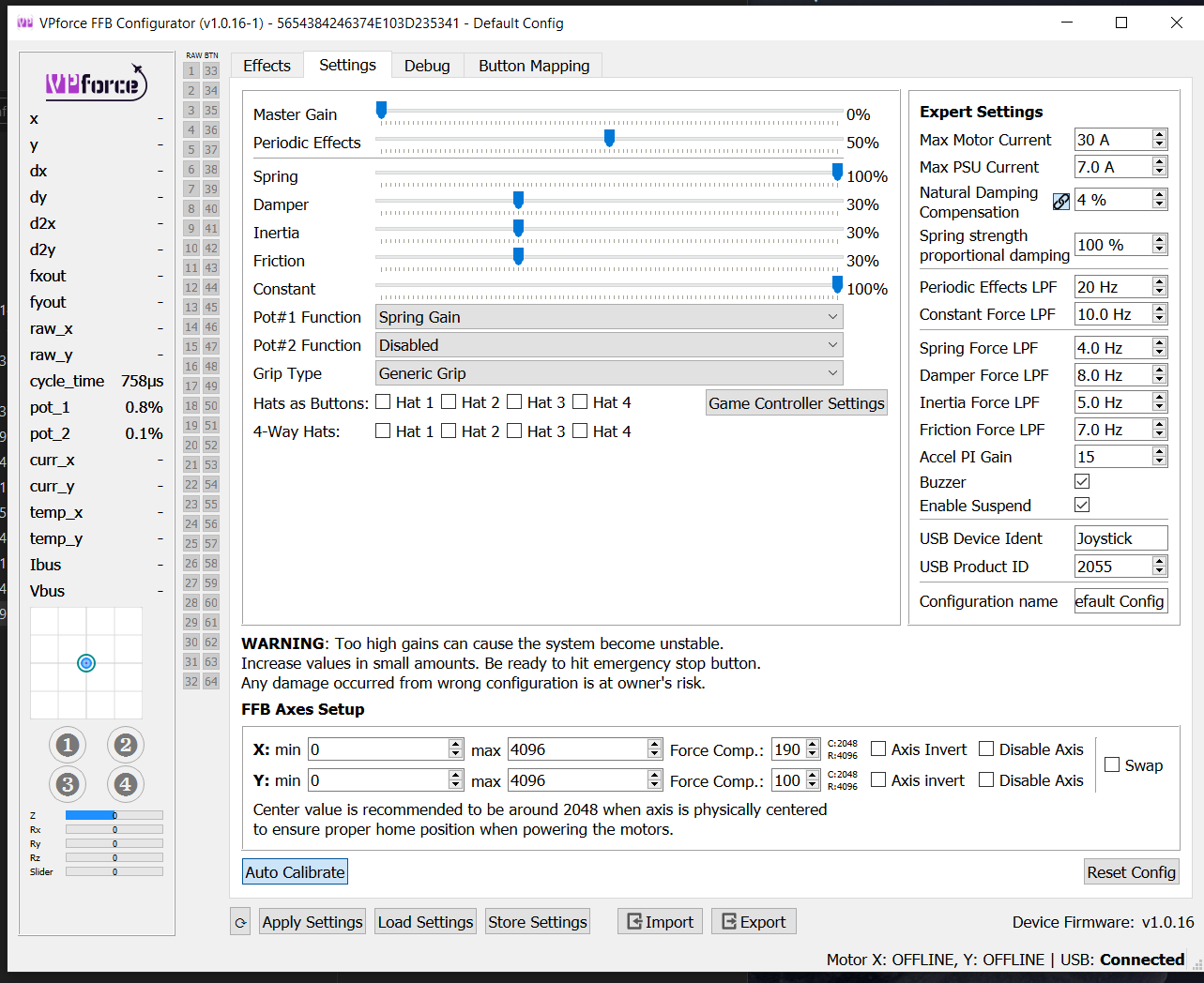 B
B NBNB
NBNB J
J


