Pay attention to the trim/position indicator - if the dot stays inside the circle centered you're go
Pay attention to the trim/position indicator - if the dot stays inside the circle centered you're golden!

 P
P . Better I should try out by myself.P
 NP
NP . I will play with the config of DCS. THX!!!
 WW
WW
 WW
WW

 PWWPPP
 SSP
SSP
 M
M SPWP
SPWP B
B TTB
TTB BT
BT TBTBB
TBTBB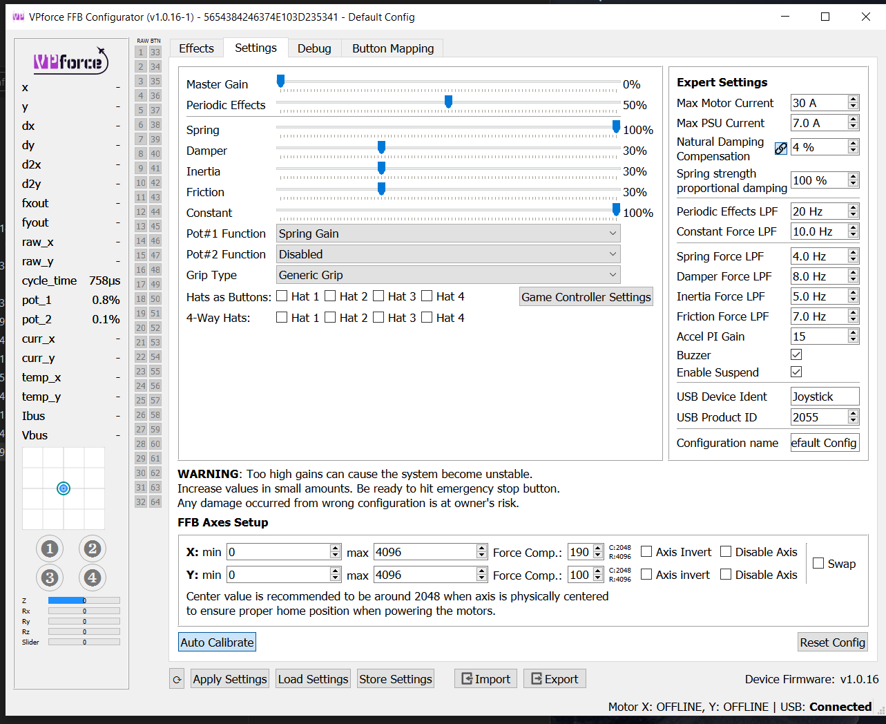 B
B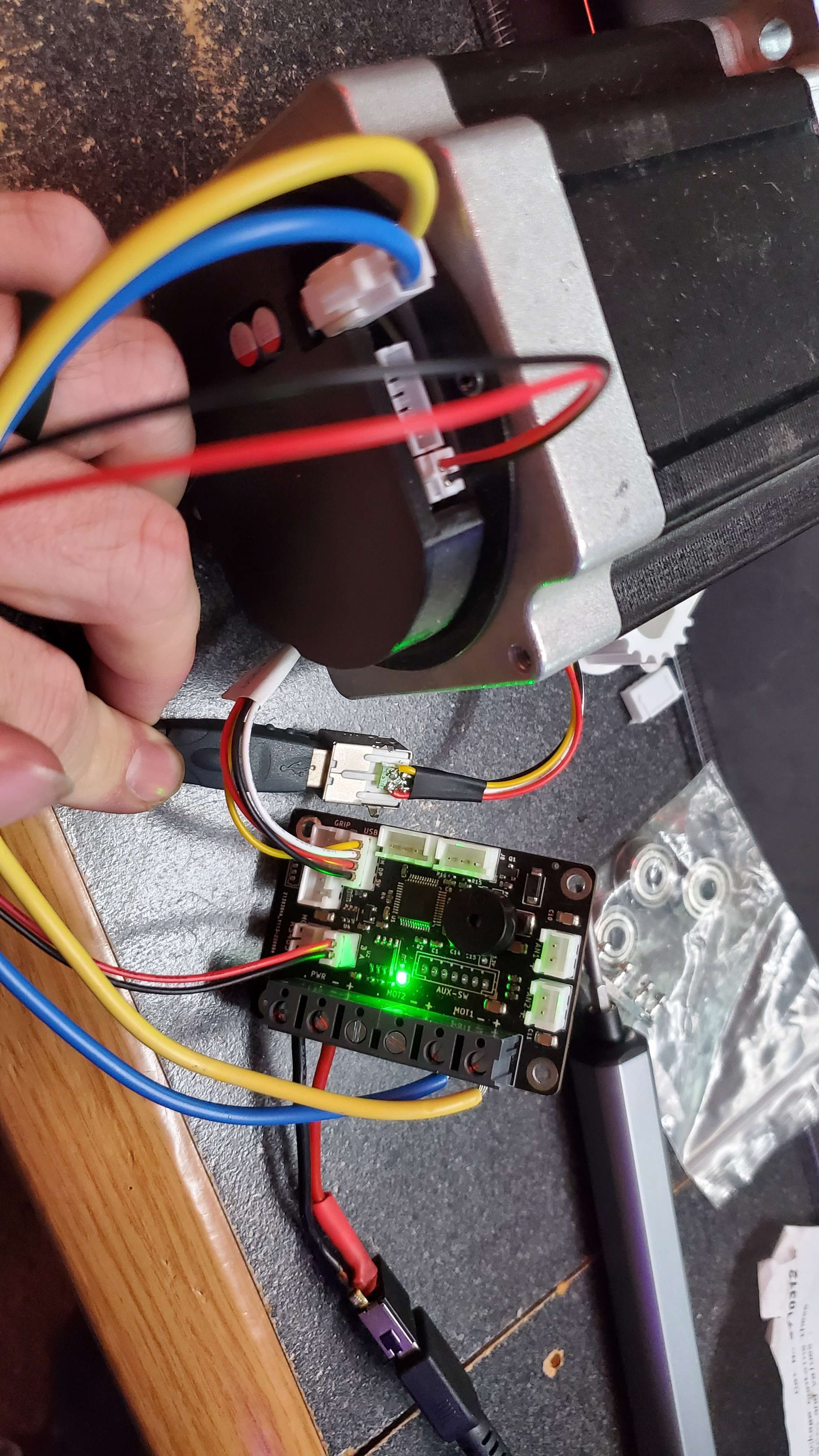 NBNB
NBNB JBN
JBN NB
NB
 NN
NN HH
HH