 W
WYou don't have to change anything more physically - your calibration is within 0-4096 bounds, which is good.
Do the auto calibration routine and save the settings.
Do the auto calibration routine and save the settings.
 P
POk, thanks.
There is no 'store center'.
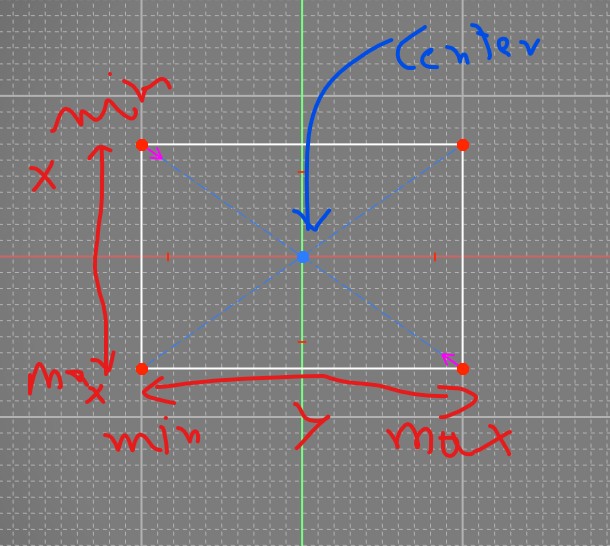
Center is computed from Xmin/max Ymin/max calibrated.
Correct ?
There is no 'store center'.
Center is computed from Xmin/max Ymin/max calibrated.
Correct ?
 A
AYes, correct. You should be able to just press "auto calibrate", read what it says in the box and press OK, move the stick forward, back, left, right, and press the auto calibration button again to exit calibration mode. Then press "store settings" for it to take effect.
Btw, personally I don't see the need of the centering tool but maybe it's me not thinking it through (as long as you are within the one rotation of the motors, at least when connecting/powering on). I didn't use the centering tool when I assembled mine but maybe I'm lucky
Btw, personally I don't see the need of the centering tool but maybe it's me not thinking it through (as long as you are within the one rotation of the motors, at least when connecting/powering on). I didn't use the centering tool when I assembled mine but maybe I'm lucky
 N
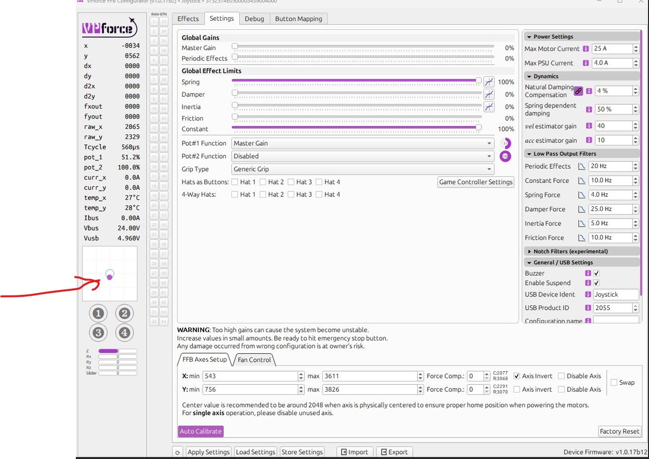
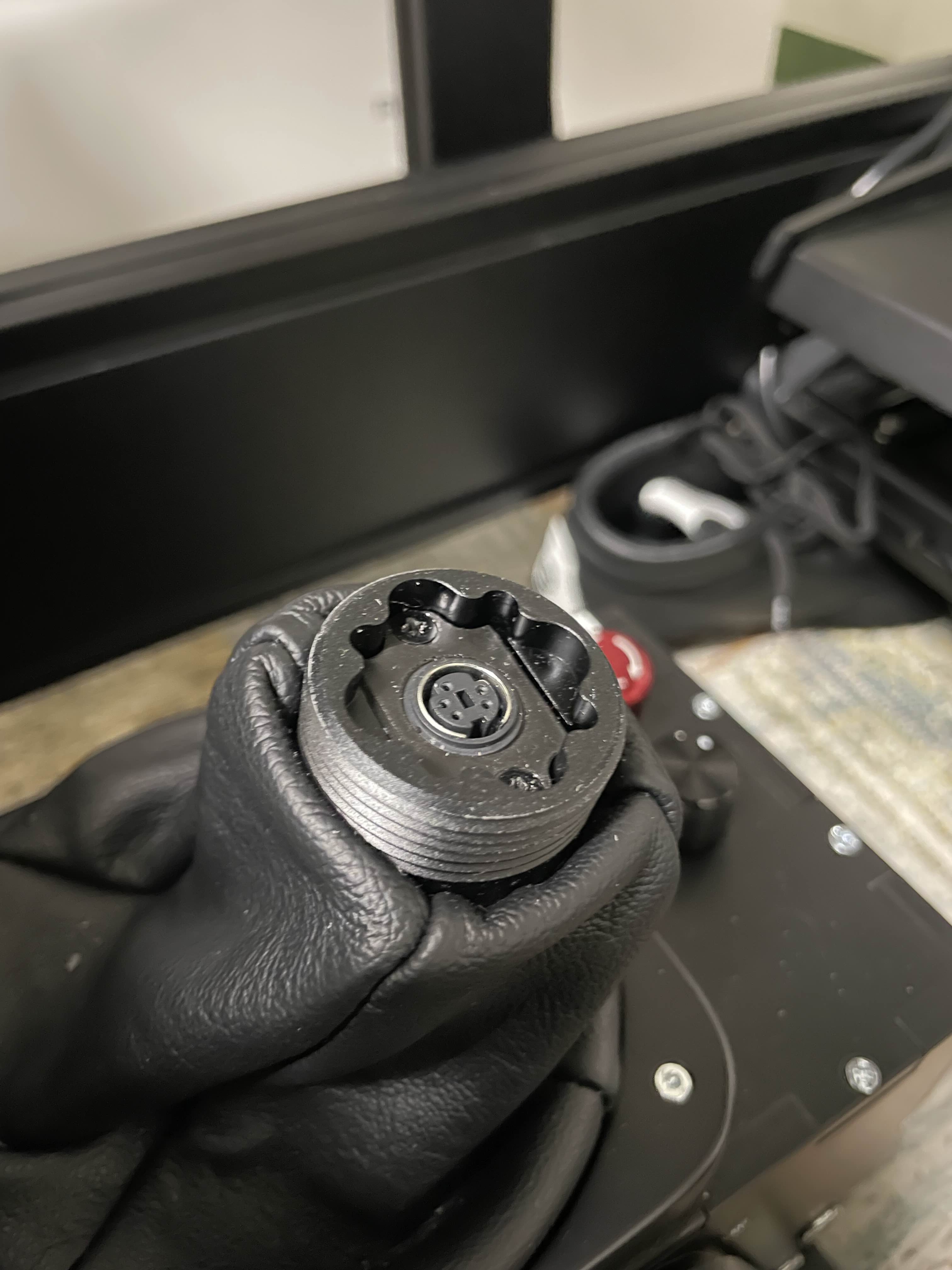
Nyour stick is sagging from center, most likely due to grip weight and extension offset (can't see what you've got attached in your photos). Also, your pot is assigned to master gain and set to %50, so you're only getting %50 of whatever spring effect strength you have started in the effects tab.
Spring is weakest at center. You should use the Balancing Procedure to counteract the sag caused by the grip. Once you have that satisfactorily configured, I recommend using the "adaptive recentering" feature in the effects tab spring settings.
Spring is weakest at center. You should use the Balancing Procedure to counteract the sag caused by the grip. Once you have that satisfactorily configured, I recommend using the "adaptive recentering" feature in the effects tab spring settings.
 B
BHi guys, does anyone has the 3D print model of the threaded insert to attach the grip when I take it out from the Rhino? I need to be taking it out frequently as I have a flight/racing sim setup and would like to have a nice place to keep the grip near the rig once I take it out instead of the floor
 B
BThank you!
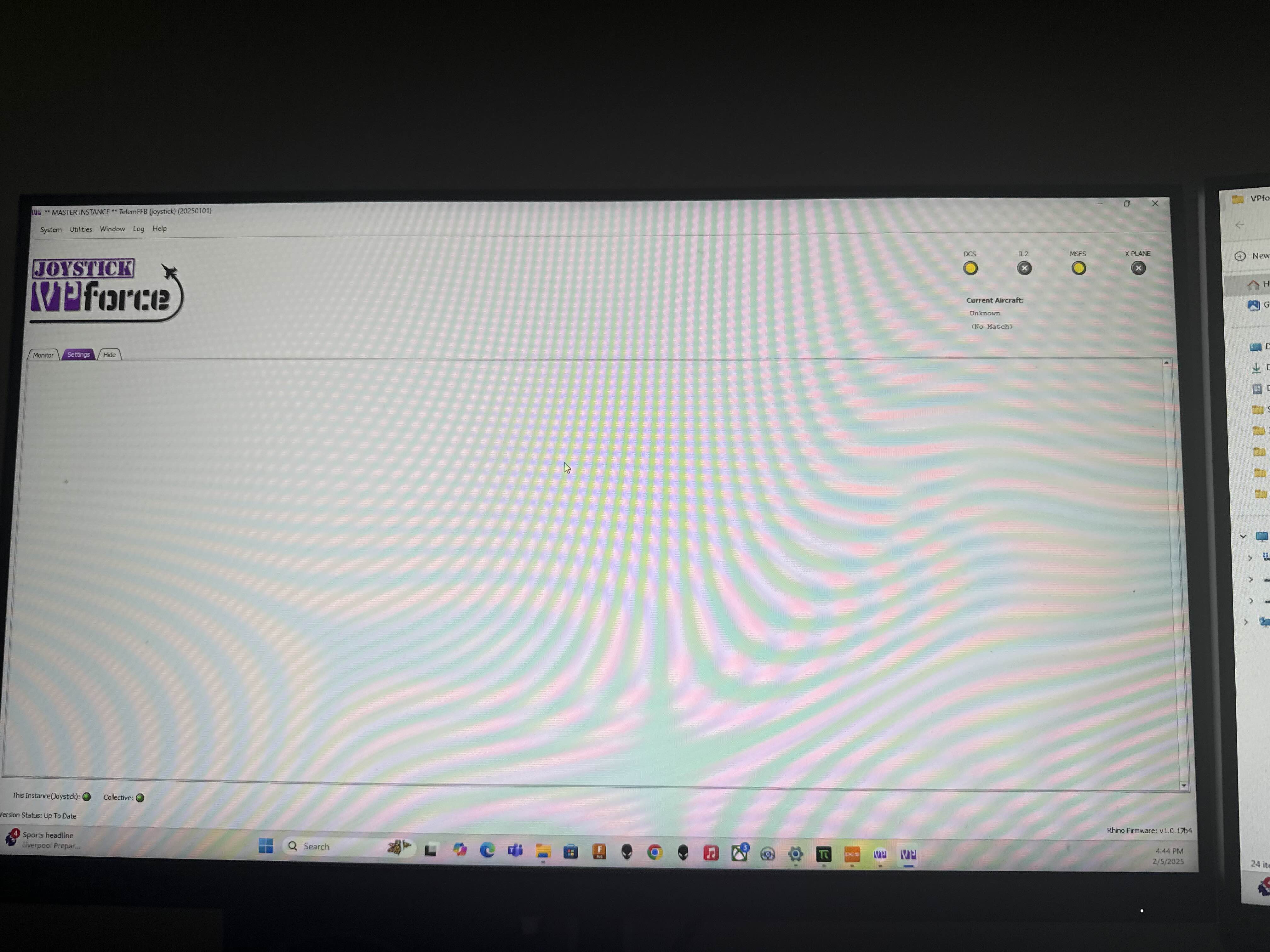
SI’m having issues with telemFFB connecting to DCS. Worked with no issues a few days ago, haven’t changed anything. Any ideas?

 D
DI'm a little stress this morning but you'll find this 3d file in this discord (sub DIY normally). Walmis had linked theses files here
 K
KDo you search this? I'm not sure if I understand you question.
https://discord.com/channels/965234441511383080/1198547200058347670/1198547200058347670
https://discord.com/channels/965234441511383080/1198547200058347670/1198547200058347670
 B
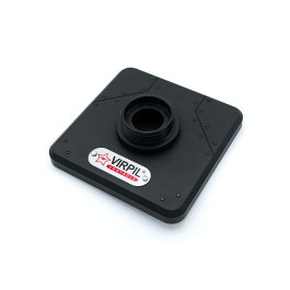
B★ Weighted display stand
★ Proudly display your VIRPIL grip collection
★ Aviation inspired design
★ Compatible with all VIRPIL grips
★ Proudly display your VIRPIL grip collection
★ Aviation inspired design
★ Compatible with all VIRPIL grips
 B
BThis is exactly what I need, thanks @kaltokri !!
 B
BNice solution, already "printed" as well, thanks @Blackrat !
 F
FThere also is a metal variant of that adapter which I would get if I would take the thing off a lot
BI did ordered that one with my Rhino, seems like it came mounted in the Rhino already
 M
MQuick support question regards the VPF shift register…….connected to VPF control board as per schematic provided on this Discord…..and checked with DIMM that connections are sound and correct.
Will it work, that is button presses register in the VP Configurator app if board is only powered by USB……..motors not yet connected with power…….i thought the board itself is powered by USB 5v and so therefore the shift register should work…..right?
Will it work, that is button presses register in the VP Configurator app if board is only powered by USB……..motors not yet connected with power…….i thought the board itself is powered by USB 5v and so therefore the shift register should work…..right?
 B
BI got the metal one anyway for longevity. plus I may swap between VKB and TM warthog.

 T
TYes, USB connection should be all you need to see button presses.
 T
T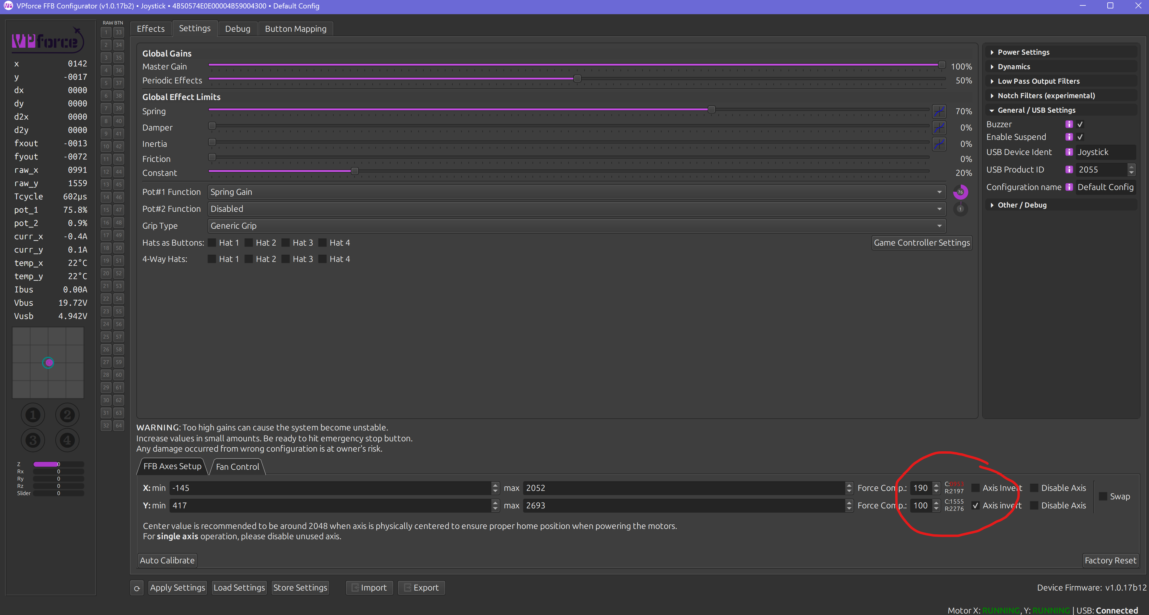 T
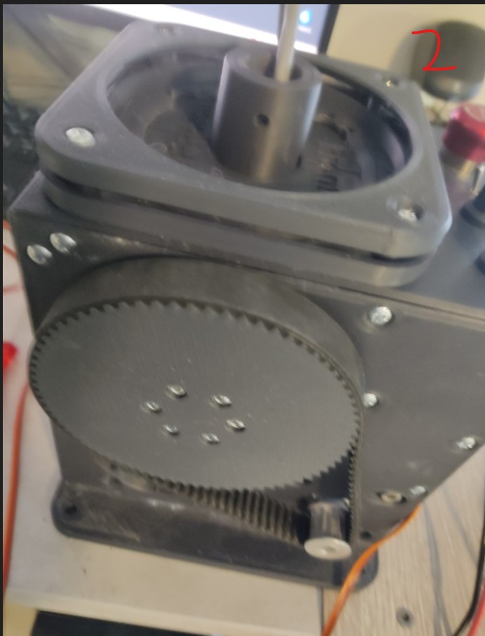
Tmy belt got loose so I tighten it up but I was a dummy and didn't hit the E stop before taking belt off so now I had to re calibrate every single profile I had... I see this number is now RED is this a bad thing?
Tit is suppose to be around 2048 right how do I fix?
 T
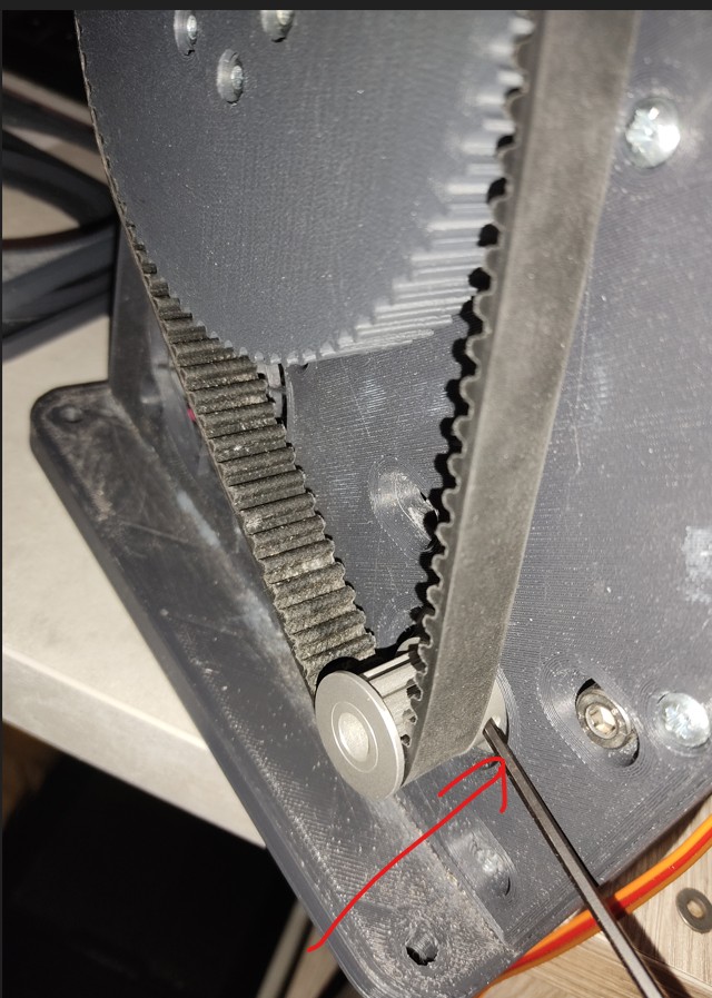
TRed number means you have a calibration value outside 0..4096. If you turned on your base with the stick in the negative X region it would not find proper center and would lock itself to one side. To fix it you would need to take the belt off, manually set the calibration range 0..4096, then put the belt back on with your stick centered.
TAnd then recalibrate
 T
Tthank you so much that worked!
MThanks…..I guess I need to check the wiring again……none show up, indicating a ground issue but I’ve checked continuity and it’s fine……mmmmm
I wired it up as per pic attached. Selected VP shift register as the grip selection……switches to ground on Shift register and to each of the 32 input positions, but nothing …….is there something else I have to enable?
I wired it up as per pic attached. Selected VP shift register as the grip selection……switches to ground on Shift register and to each of the 32 input positions, but nothing …….is there something else I have to enable?
M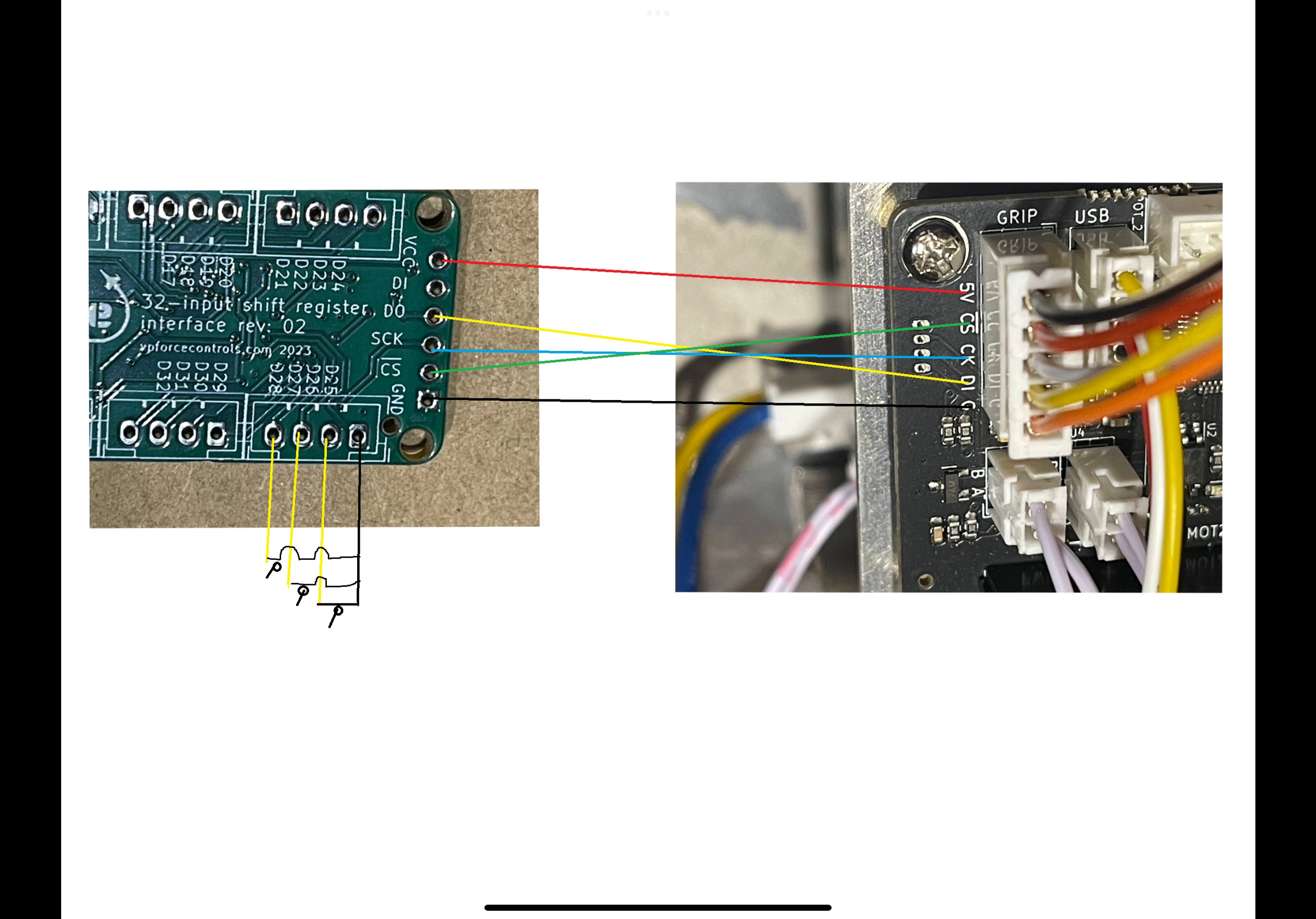 T
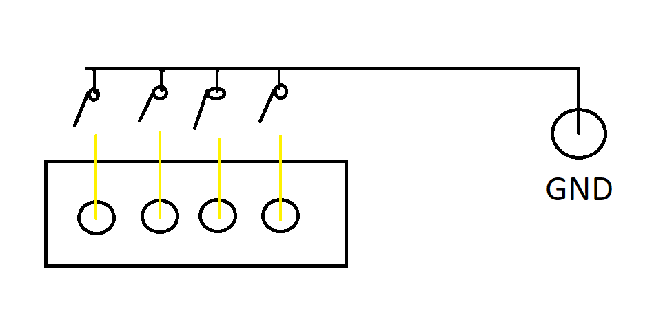
TButton wiring is the issue. Each of those 4 pins are buttons. They connect to the ground from the VPF main board. So in your pic you have
yellow/yellow/yellow/black
but in reality it’s
yellow/yellow/yellow/yellow to separate GND
yellow/yellow/yellow/black
but in reality it’s
yellow/yellow/yellow/yellow to separate GND
TIf that makes sense
Tsorry for the crude drawing
 M
MActually as per your pic is how it’s wired…….the pic I posted was from a pic I downloaded from somewhere else on this discord to help with how the connection between shift register and VP control board. My switches are all connected to ground in series and the other side of switches to respective input on Shift register sequentially. So if there is no other requirement to do, it must be either board faulty or I’ve connected something wrong???
M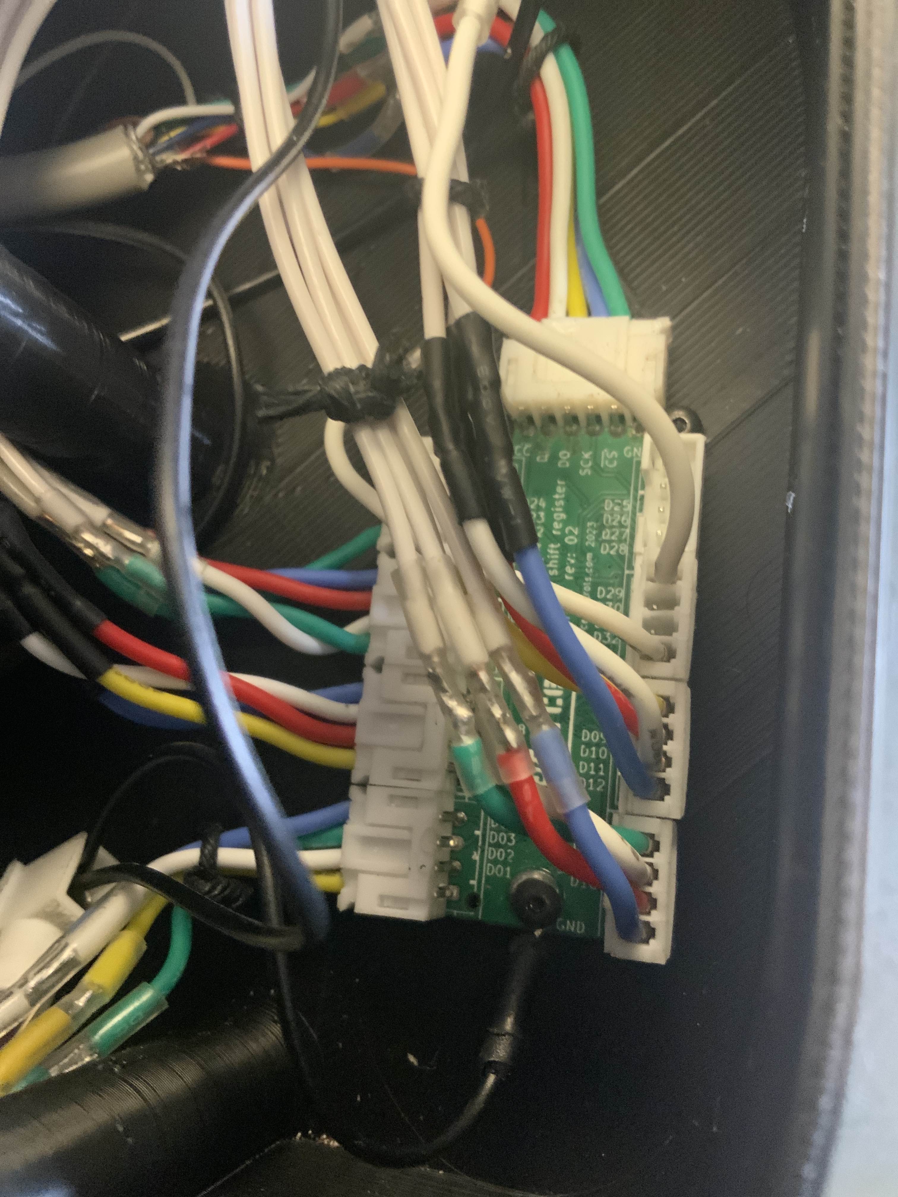 T
TOn the 6 pin input connector I see 5 wires which is correct but it looks like they are in positions 1-5? Hard to tell so maybe not but are you sure that is all correct? Looks like it’s missing GND but maybe that’s on the screw terminal?
TIt looks like DI is connected for some reason.
TMaybe I see a GND wire hiding back there.
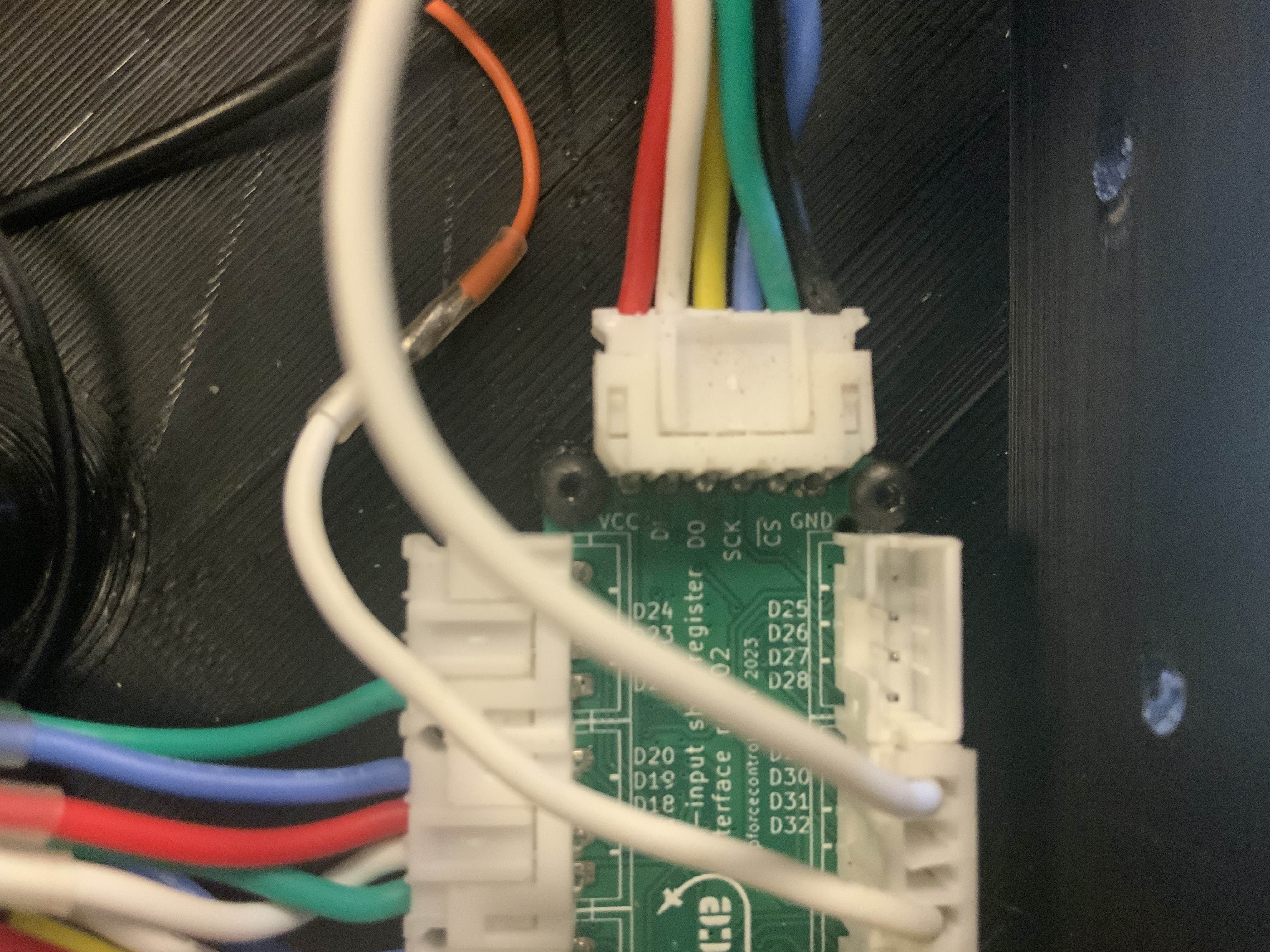
MHere is a better pic……D1 is wired but goes nowhere as not used…..D0 goes to D1 on VPF board. I’ll recheck connection between boards again.
 T
TOk I see it. If the buttons are as the drawing I posted and board to board is correct it has to be an issue with the grounding or the board to board connections. This might be a dumb question but is the GND used for buttons connected to the same GND used for the board to board connection?
TA pic of the configurator debug tab with the debug grip option selected may help troubleshoot also.
 N
NMy natural damping compensation value is set at 20%, that way I feal stick moving without any resistance. Is it normal such high value providing that the default is 4%( I am using 86bl04 engines)?

 S
Sif that's what it takes, nothing wrong with that. tune to your hardware, not everyone elses.
N
 W
Whello everyone,
can you confirm to me that there will be no risks, because I am about to connect my rhino VPforce for the first time, with my meanwell 360w 16A only to power my rhino for the moment?
Commentaires
can you confirm to me that there will be no risks, because I am about to connect my rhino VPforce for the first time, with my meanwell 360w 16A only to power my rhino for the moment?
Commentaires
 C
C
 G
G@walmis I've just ordered another pair of motors from yourselves, and a spare FFB circuit board, is it possible that you could add to the invoice and include a spare USB connector cable and PCB plug?
 B
BI have a 350w 14A meanwell with the rhino hooked up at 8amps and the rhino MFG at 4 amps, my understanding is that the device will only draw the amps it needs.
BBut there is always a risk whenever you hook power up 
Wok okay, I didn't understand that, that's great thank you very much
BBut like all these things, its your responsibility 
BWelcome to DIY bespoke hardware
BMaybe list your meanwell here?
 F
FHey Mike, I'm building a custom H135 cyclic right now and encountered the same issues. checked everything twice redid all my connection; I was able to measure 5v coming all the way through my buttons. What I didn't know; you need to apply 24v to the rhino too to have the button presses registered. I hope that fixes your problem as well!
 T
TI just spent the last hour on DCS messing with SRS binds on a hat switch of my stick with no power to the base other than USB connection.