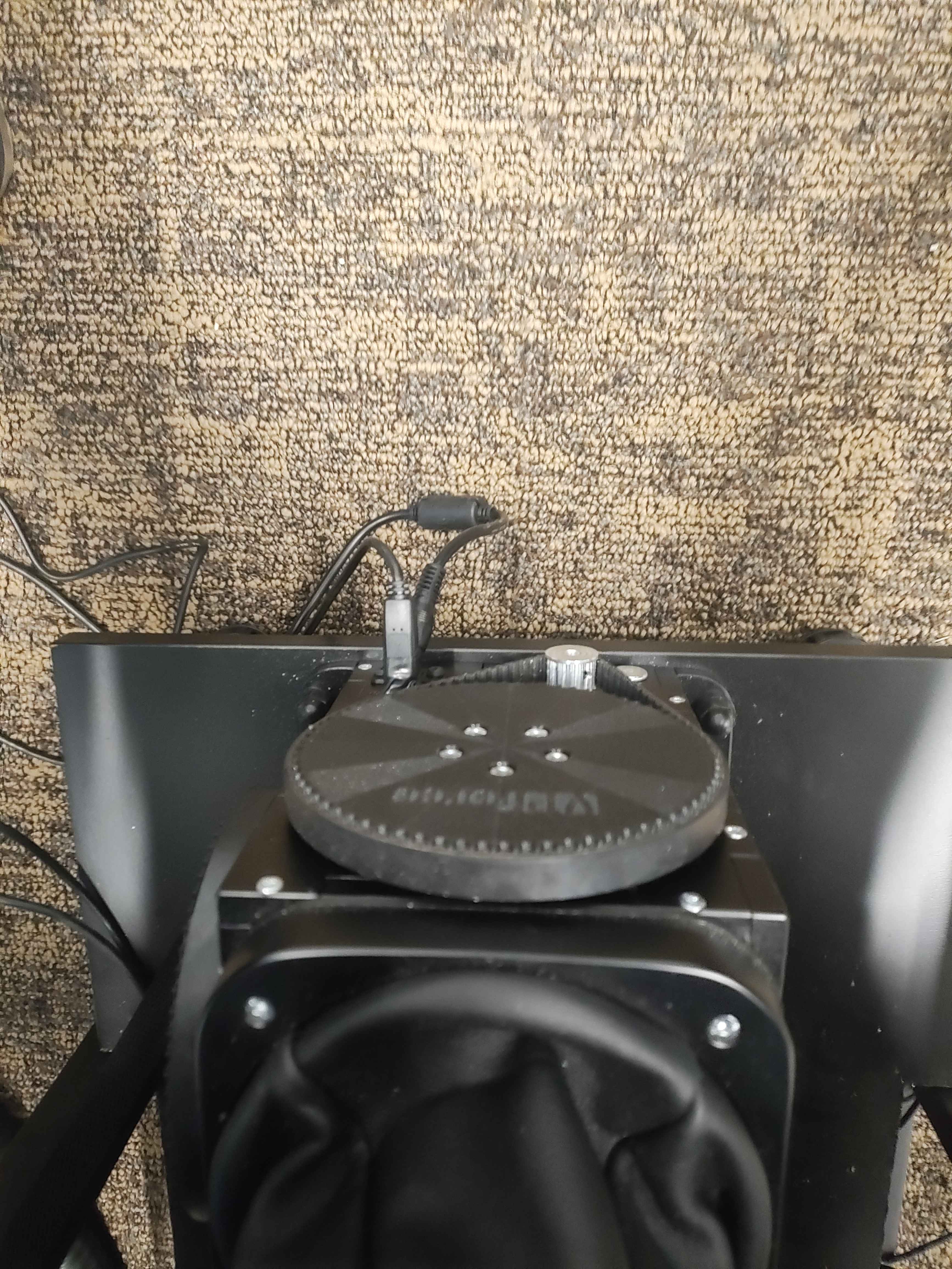
it's the cables... I have to rotate base for 180 and flip pitch axis... cause this way me or my son
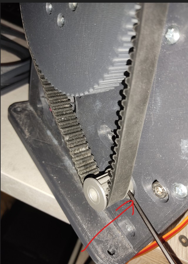
it's the cables... I have to rotate base for 180 and flip pitch axis... cause this way me or my son always nudge the cables acidentally... 
 K
K J
J B
B
 F
F F
F AA
AA P
P WPWPPP
 WP
WP
 A
A
 N
N B
B BS
BS
 DKB
DKB BB
BB FB
FB MB
MB T
T T
T TTTTTMM
 TTT
TTT MM
MM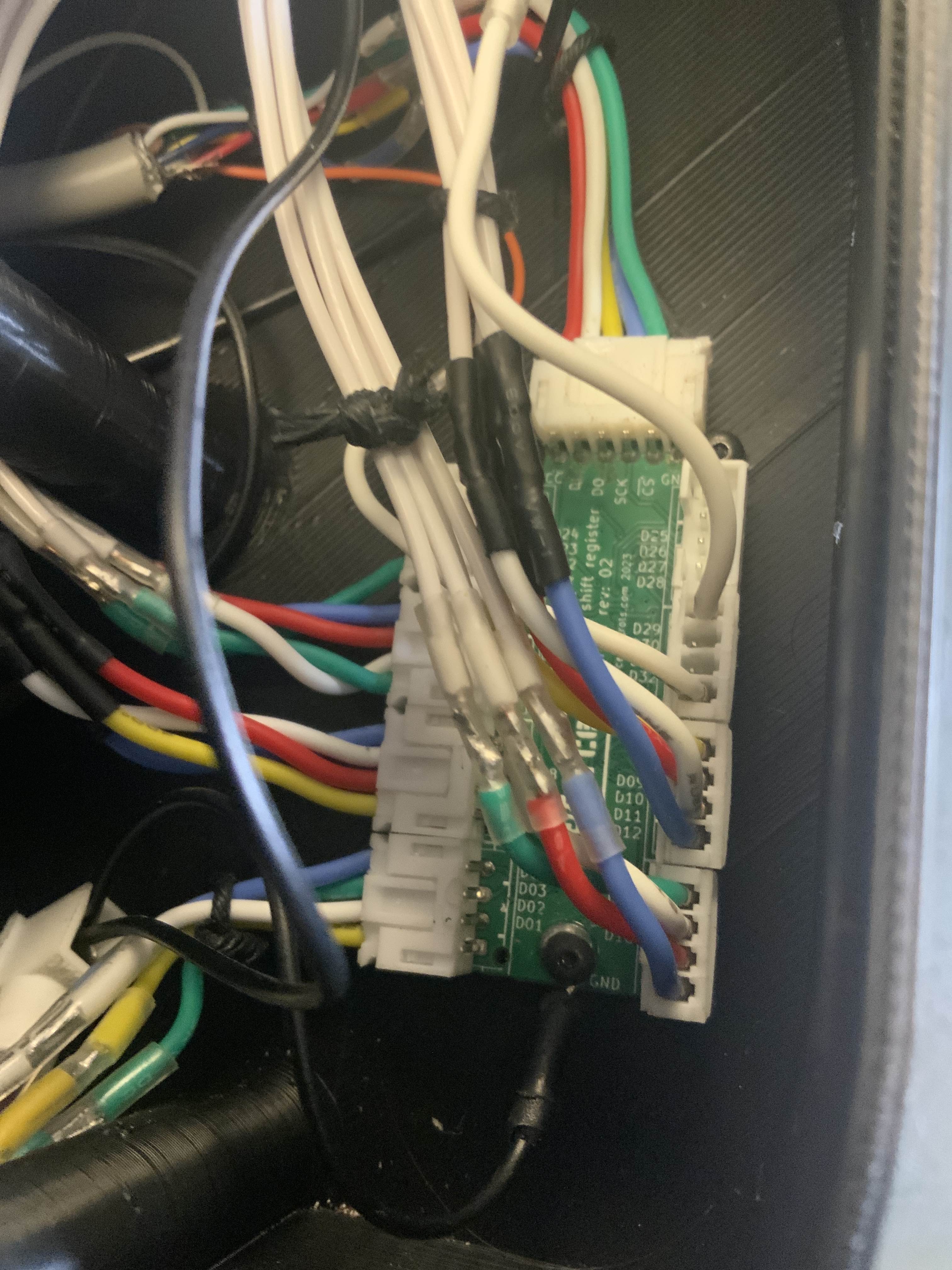 TTTM
TTTM TT
TT


